
Peter Daniel said:I see you've implemented Peranders suggestions, right? 😉
Not quite, as he was inserting the snubber on the chip's pins (after the caps), and he was using the same values as on the PSU.
And he doesn't use bypass caps.
Let's say that P-A knows this snubber circuit from me, no?
But well, I've been thinking in trying this, and it works.
Not a big improvement as the first snubber provides, but an extra degree of midband and treble detail.
The midband is gorgeous.

Can someone suggest a "hack" to integrate this snubber update onto Brian's LM3875 Rev3 or LM3886 boards? Im trying to figure it out, but im lost
also MKT caps? is this the same as metallized polypropylene, ie the blue BC caps included in Brian's kits?
also MKT caps? is this the same as metallized polypropylene, ie the blue BC caps included in Brian's kits?
homer09 said:Can someone suggest a "hack" to integrate this snubber update onto Brian's LM3875 Rev3 or LM3886 boards? Im trying to figure it out, but im lost
I don't see where's the problem...
On the film cap's place use the 100uf electrolythics.
Bypass the electrolythics directly under them, under the board.
On the bigger holes for the 1500uf caps insert the snubber.
homer09 said:also MKT caps? is this the same as metallized polypropylene, ie the blue BC caps included in Brian's kits?
Those are fine.
homer09 said:Can someone suggest a "hack" to integrate this snubber update onto Brian's LM3875 Rev3 or LM3886 boards? Im trying to figure it out, but im lost
also MKT caps? is this the same as metallized polypropylene, ie the blue BC caps included in Brian's kits?
MKT is polyester film.
Regarding using Brian's kit, the 3886 power supply and presumably the new LM3875 snubberized kit have the parts and boards to do the traditional snubber (Oh so January 🙂 ) that is the schematic that Carlos posted. So that part is in good shape.
The change that Carlos is recommending is adding a few things at the chip and is in the comments.
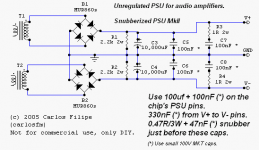
The 100Uf and 100nF is already there sort of. The 100uF caps are included in the 3886 kit for example. The 100nf is a polypropylene box in the 3886 kit. So you would need to use a 100nf MKT (polyester) instead that was not in the kit. So the holes are there but you would need to add this part ( quantity 4 - 2 for left, 2 for right amp )
The 300nF from V+ to V-. THis you would need to add. You would need 2 of these, one for each channel. I would expect to be able to just let the 3886 pins hange down below the board and solder to those underneath the board. Perhaps use a bit of insulation from some scrap wire to insulate each leg of the cap if it has to span across any traces.
For the snubber of 0.47/3w + 47nF: You have to add this. You would need 4 of these snubbers. Hmmm. What about going from the V+ in to CHG (?) underneath the board. Again some insulation from some scrap wire likely will be needed. Do the same for V- to CHG.
Edit: Carlos' method is cleaner, I would think for a new board that is not yet populated,
OK some questions for Uncle Carlos (or anybody else who would like to answer them).
We now have two snubbers between the 10,000uF caps and the 100uF caps on the pins of the chip. Why is that and could these not be combined into one?
Why is the 0R47 resistor specified as 3W when the 1R is specified as 2W? Is this because you can only find the 0R47 in 3W wirewound? If so could we use a pair of 1R/1W resistors in parallel?
We seem to be adding a lot of polyester caps into the circuit and I have always understood these to be inferior to the polypropylenes. I presume that the polyesters are specified here for their comparitvely smaller size. Has anybody tried the mettalised polyphenylene sulphide caps? 😎
The min rating of this resistor is << 0.6 watts => a plain 0.6 watt metall film will do and you will also get a "purer" resistance, only advantages.Nuuk said:Why is the 0R47 resistor specified as 3W when the 1R is specified as 2W? Is this because you can only find the 0R47 in 3W wirewound? If so could we use a pair of 1R/1W resistors in parallel?
I have used 3 x 1206 10 ohms and those aren't burnt yet.... see picture below, R9-R11
Don't forget that high resonance frequency is one good property and big polyprops have lower resonance frequency than small polyester ones.Nuuk said:We seem to be adding a lot of polyester caps into the circuit and I have always understood these to be inferior to the polypropylenes. I presume that the polyesters are specified here for their comparitvely smaller size. Has anybody tried the mettalised polyphenylene sulphide caps? 😎
I have tested PPS caps but only as input coupling caps. The are too big for ordinary decoupling. For this purpose I use 100 nF X7R 0805 size.
C1 in the picture is PPS, C8, C9 are X7R.
An externally hosted image should be here but it was not working when we last tested it.
I think that we need to specify if we are talking SMD or standard components here! I believe that most of us are not using SMD!
The PPS are no bigger than the polysester caps in standard format.
And with the 047R, it's a question of finding that value in other than a wirewound 3W.
The PPS are no bigger than the polysester caps in standard format.
And with the 047R, it's a question of finding that value in other than a wirewound 3W.
... no, no, it's just a coincidence.Peter Daniel said:I see you've implemented Peranders suggestions, right? 😉

Still I want the unsnubbed 100 nF to be removed according to my "enhanced" PS. Why? This cap still produces a peak which is easy to measure and the snubber was to remove those peaks. Note that I haven't put any level of importance of this. It's just visible and you can measure it.
My rather uncommented idea is here and the schematic is here
Feel free to evaluate my idea. Is it an enhancement or doesn't it matter really?
Any comment about my last post?
http://www.diyaudio.com/forums/showthread.php?postid=603730#post603730
PPS are a bit worse in some parameters than polyprop but I'll guess they are alright if you compare.Nuuk said:I think that we need to specify if we are talking SMD or standard components here! I believe that most of us are not using SMD!
The PPS are no bigger than the polysester caps in standard format.
And with the 047R, it's a question of finding that value in other than a wirewound 3W.
Snubber resistor power.
Ripple voltage U at 20 kHz (just an assumption, far from reality): 1 volt
C = 100 nF
f= 20 kHz
R= 1 Ohms
P = ((U*2*pi*f*C*R)^2)*R => 158 microwatt! in this really harsh case much harder than real life.
Nuuk: 0207 = 2 x 7 mm => plain 0.6 watter (this is confusing when you are mixing mils and mm)
0207 is mark of industry standard resistors, which you can buy in every stores. Their definition is 0.6 W, 1 %, low inductance, raster 10 mm ( body 6.8 mm ). Example : 0207 4k7 😎
0207 is mark of industry standard resistors, which you can buy in every stores. Their definition is 0.6 W, 1 %, low inductance, raster 10 mm ( body 6.8 mm ). Example : 0207 4k7
Thanks again. I have been through the Farnell catalogue and they don't have any values under 1R for the standard resistor ranges. That's why I asked about using two 1R's in parallel. 😉
noob question
OK I searched for an hour or so, but I cannot find an answer. Please forgive me if this is very basic as I am a beginer.
When wiring a this or any other dual rail power supply is using two single secondary transformers acceptable, or will it even work? Or do you have to have dual secondaries.
The reason I ask is I happen to have two 300VA 24V single secondary transformers I would like to use to implement this PS.
Please be kind I did search.
Russ, that will work fine. Just pretend they are dual secondaries🙂The reason I ask is I happen to have two 300VA 24V single secondary transformers I would like to use to implement this PS.
Steen.
- Status
- Not open for further replies.
- Home
- Amplifiers
- Chip Amps
- The (high-cap.) unregulated PSU for chipamps