These are watermarked hifidiy.net images. Do they really refer to your query or are they meant to illustrate something else? To address your question though, both images show a harmonic bump at approximately -90dB with respect to the reference signal level. The "problem" you see is most likely due to the different scaling, shown on the left side of the images. The major difference between the simulations is actually the noise floor, which (as I now noticed tikiroo had stated) is significantly lower in the second image, whilst the harmonic levels may not have changed much at all.
It would help to have a link to the article to know all that the author was talking about.
It would help to have a link to the article to know all that the author was talking about.
Sorry, I sent out a request for help elsewhere and didn't get an accurate answer. I forgot to deal with the watermark. Please forgive meThese are watermarked hifidiy.net images. Do they really refer to your query or are they meant to illustrate something else? To address your question though, both images show a harmonic bump at approximately -90dB with respect to the reference signal level. The "problem" you see is most likely due to the different scaling, shown on the left side of the images. The major difference between the simulations is actually the noise floor, which (as I now noticed tikiroo had stated) is significantly lower in the second image, whilst the harmonic levels may not have changed much at all.
It would help to have a link to the article to know all that the author was talking about.
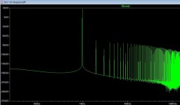
I want to know why a resistor connected in parallel will bring so much bottom noiseThe harmonics haven't disappeared, the noise floor just raised to hide them.
Thank you for your reply
It looks very much like the amplifier hasn't settled well enough in the case where you see the high floor (which isn't really a noise floor, but just the FFT trying to approximate a periodic continuation of the settling waveform).
The 30 ohm resistor is marked 0.1 on the schematic. Does that mean you use 0.1 ohm in the case with the low floor?
There are two things in your circuit that can cause slow settling, the DC coupling capacitor and the DC bias loop (it's my favourite type of bias loop, by the way). When you short the coupling capacitor, you eliminate the effect they have on the circuit. 0.1 ohm is almost a short.
I think you need to run a much longer simulation and only use the last part for the FFT. That should eliminate the "noise".
By the way, doesn't the 100 nF capacitor across the inputs of U1 cause stability issues?
Last edited:
I overlooked R22. Shorting the DC blocking capacitor does not eliminate the effect of the DC bias loop.
The schematic and measurements probably come from here:It would help to have a link to the article to know all that the author was talking about.
Hifidiy
In post #16 of this thread a forum member thinks the change in noise floor is the explanation, just like you do.
I had another look at the circuit and came up with a new hypothesis:
I still think the FFT floor is due to settling issues.
When you short the 2.2 uF, either with a hard short or with 0.1 ohm or with 30 ohm, the DC loop becomes quite slow. If I reverse-engineered the circuit correctly, you get first-order behaviour with a time constant of 2.635 seconds. It could be that with such a large time constant, the shift in DC over a few cycles of your signal is too small to affect the FFT floor much.
When you don't short the capacitor at all, the loop becomes much faster. The DC shift within a few signal cycles then also gets larger and affects the FFT floor more. Solution: give the amplifier time to settle.
When you give the amplifier 30 seconds to settle, so simulate over a bit more than 30 seconds and throw away the first 30 seconds, the difference should disappear. It may already disappear with shorter settling times.
当您根本不短路电容器时,环路会变得更快。然后,几个信号周期内的 DC 偏移也会变大,并更多地影响 FFT 本底。解决方法:让放大器有时间稳定下来。
Thank you for your analysis. I think I understand what's going on.I had another look at the circuit and came up with a new hypothesis:
I still think the FFT floor is due to settling issues.
When you short the 2.2 uF, either with a hard short or with 0.1 ohm or with 30 ohm, the DC loop becomes quite slow. If I reverse-engineered the circuit correctly, you get first-order behaviour with a time constant of 2.635 seconds. It could be that with such a large time constant, the shift in DC over a few cycles of your signal is too small to affect the FFT floor much.
When you don't short the capacitor at all, the loop becomes much faster. The DC shift within a few signal cycles then also gets larger and affects the FFT floor more. Solution: give the amplifier time to settle.
When you give the amplifier 30 seconds to settle, so simulate over a bit more than 30 seconds and throw away the first 30 seconds, the difference should disappear. It may already disappear with shorter settling times.
Thank you.
Are you using a sensible window with the FFT? If you don't use a window (aka rectangular window) the circuit has to be strictly periodic with the FFT rate (which it won't be due to the long time constants). So you need to use an FFT window.
The smooth looking floor is a strong hint of no window - normally the noise floor is (surprise surprise) noisy....
For accurate measurements of peaks use a flattop window, for general use the Hann window is pretty good.
The smooth looking floor is a strong hint of no window - normally the noise floor is (surprise surprise) noisy....
For accurate measurements of peaks use a flattop window, for general use the Hann window is pretty good.
So for instance this signal is not periodic due to some RC time constant:

So its straight FFT sees a discontinuity at the wrap-around, leading to lots of broadband energy:

But with a Hann window the discontinuity is removed allowing the actual useful spectral data to be visible:

Note that the harmonic peaks were mainly masked without a window and the floor is no longer suspiciously smooth.
The actual circuit was an RC filter:

The simulation allowed 2ms for the circuit to reach DC stability, but that's only 2 time-constants and not enough.
The issue is that the discrete Fourier transform is only defined for exactly infinitely repeating waveforms - which never exist in
reality, and often not in simulation either, so we have to apply a windowing function to make it more meaningful (its basically a hack,
but an extremely useful one).
All spectrally useful windows taper the response to zero at either end of the waveform to remove discontinuities - there's an
art to choosing the right window (for instance for measurements only flattop windows give accurate signal peak values, and
when you are interested in the noise floor simpler windows like the Hann window give more information).
Many tools have a paucity of good flattop windows - this paper is an invaluable resource about FFT in general and is by far the
best discussion of windowing functions out there: https://holometer.fnal.gov/GH_FFT.pdf
So its straight FFT sees a discontinuity at the wrap-around, leading to lots of broadband energy:
But with a Hann window the discontinuity is removed allowing the actual useful spectral data to be visible:
Note that the harmonic peaks were mainly masked without a window and the floor is no longer suspiciously smooth.
The actual circuit was an RC filter:
The simulation allowed 2ms for the circuit to reach DC stability, but that's only 2 time-constants and not enough.
The issue is that the discrete Fourier transform is only defined for exactly infinitely repeating waveforms - which never exist in
reality, and often not in simulation either, so we have to apply a windowing function to make it more meaningful (its basically a hack,
but an extremely useful one).
All spectrally useful windows taper the response to zero at either end of the waveform to remove discontinuities - there's an
art to choosing the right window (for instance for measurements only flattop windows give accurate signal peak values, and
when you are interested in the noise floor simpler windows like the Hann window give more information).
Many tools have a paucity of good flattop windows - this paper is an invaluable resource about FFT in general and is by far the
best discussion of windowing functions out there: https://holometer.fnal.gov/GH_FFT.pdf
Last edited:
Of course, it also depends on the cap model. Other than just getting the circuit working, you then need to go in and start adding more realistic models or adding parasitics yourself. Power supplies that are not perfect, source impedance, better load simulation etc.
Inaccuracy in the simulation.Why does your RC filter distort?
Usually in LTspice it's because either the simulation isn't long enough (not enough cycles of the fundamental), timestep too large, or compression (tools -> control panel -> compression, untick all compression options)
-80dB is 0.01% voltage accuracy. Should be able to push that out to at least -160dB / 0.000001% accuracy by following the above.
- Home
- Amplifiers
- Solid State
- the harmonics did disappear. What is the reason