You have a good point, but I think the key is READ, then ask questions until you have a grasp on the basics. Comparisons with plumbing systems can be a great help with understanding basics.
Bill
Bill
Here are all of Professor's questions:
Okay then. To aid your comprehension, hot wire=mains wire=live wire. They are all the same thing. You probably knew this, but just in case.
1: Ground is usually the reference point for a probe. It makes it easy to check circuit voltages if you always have the black (negative) probe touching ground, and all you have to do is go through a list of touching the red probe to the different parts of the circuit. The ground terminal is simply there for convenience, it doesn't make that part of the circuit special except in that the ground is usually connected to the chassis or a cold water pipe or the third hole on the wall plugin. For example:
The reason the ground point is usually connected directly to the power supply instead of right in the middle of a circuit is that we can't predict how much stray capacitance is connected to ground simply because ground is connected to a whole lot of metal. If we connect this to a sensitive part in the circuit, all that extra capacitance will cause lots of problems. And imagine what happens in a lightning storm! If it is connected to the supply we don't have to worry much about what effect it will have on the circuit.
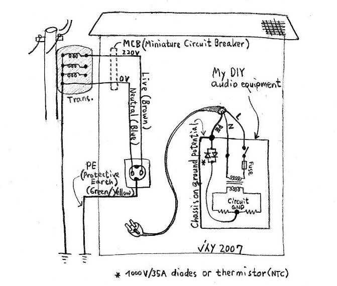
2: That's backwards. Whenever current flows through a resistor, it develops a voltage difference across the resistor. Since no conductor is perfect, all conductors have a small amount of resistance. The neutral wire in a power socket always has electricity flowing through it back to the power plant. And because there is a LOT of wire between those two, a large amount of current can cause a large voltage potential between those two places. This causes the neutral wire to become unsafe, even though it is connected to ground. The ground wire almost NEVER has current flowing through it, so there is no voltage to make it unsafe. If your circuit blows up and draws an enormous amount of current, your chassis would be unsafe if you connected it to the neutral. But if you connect the chassis to ground, it will lower the voltage potential because there is much less current flowing through the ground wire and it will make your chassis safe to touch. Usually the neutral and hot wires are isolated from the chassis through a transformer for even more protection from the voltages that arise when too much current flows through too small a wire.
2a: If you pick two points on a conductor and measure the voltage, it will be zero. Unless there is a massive amount of current flowing through that conductor. In this case there will be a voltage between those two points because of the voltage developed across the resistance. With AC this is no different than with DC. The only difference is that with AC, the voltage potential will switch polarity when the current flow changes direction.
3: I can't tell from your description what he meant. I might go read it later.
4: The hot line has more potential to ground than the neutral line does. So it is much more likely that the mains line will pass an unsafe amount of current than the neutral line will if there is a short to ground. So generally we like to keep the mains as far away from ground as possible.
Now look at this picture again. Say that the neutral is shorted to the live wire. What happens? What if neutral is shorted to ground?
I'm fairly sure I didn't make a mistake. Hopefully someone will catch me if I did.
I hope this works for you,
- keantoken
1) In an electric circuit, we can have plus, minus or a centre tapped zero point and a plus and minus. This is so that current can flow from plus to minus. However, often, the minus is also shown as ground on the circuit diagram. What does that mean?
2) I have never understood how a ground loop works despite reading up on it dozens of times. My understanding is that a ground loop is nothing but a differential in potential which causes current to flow. Where and how does this potential difference arise?
........2a) I'm not sure I follow what youre saying. I agree that any
........conductor will have a small resistance. But if we pick 2 points on
........that conductor why should they be at different potentials?
................2b) yes however that's precisely my question. WHY should
................there be current flowing? I dont get that. Just to be clear, we
................are considering a piece of metal yes? and we are saying that there is a current flow between any two points? Thats curious.
3) In that article by Pass, it states to keep all the length of wires to the single ground point of equal length. But how would this be possible given that the wires all originate from various parts in the circuit? For example one wire might be from the power transformer in which case the wire is as long as the coil. Another wire might originate from the negative rail of the speaker output (say on an amplifier) in which case again, the length is arguably the length of the loudspeaker cable and even the coil and so on.
4.) The article also states that we should not swap neutral and live since the fuse would then also be swapped. My understanding is that the mains supply is to all intents a symmetrical supply, roughly that of a sin wave which we know is periodic and so should not make any difference which way we plug it in?
........4a) I still dont get why we shouldnt swap them. Please
........explain to me. My understanding is that Live and neutral are
........just names for two arbitrary points.
Okay then. To aid your comprehension, hot wire=mains wire=live wire. They are all the same thing. You probably knew this, but just in case.
1: Ground is usually the reference point for a probe. It makes it easy to check circuit voltages if you always have the black (negative) probe touching ground, and all you have to do is go through a list of touching the red probe to the different parts of the circuit. The ground terminal is simply there for convenience, it doesn't make that part of the circuit special except in that the ground is usually connected to the chassis or a cold water pipe or the third hole on the wall plugin. For example:
The reason the ground point is usually connected directly to the power supply instead of right in the middle of a circuit is that we can't predict how much stray capacitance is connected to ground simply because ground is connected to a whole lot of metal. If we connect this to a sensitive part in the circuit, all that extra capacitance will cause lots of problems. And imagine what happens in a lightning storm! If it is connected to the supply we don't have to worry much about what effect it will have on the circuit.
2: That's backwards. Whenever current flows through a resistor, it develops a voltage difference across the resistor. Since no conductor is perfect, all conductors have a small amount of resistance. The neutral wire in a power socket always has electricity flowing through it back to the power plant. And because there is a LOT of wire between those two, a large amount of current can cause a large voltage potential between those two places. This causes the neutral wire to become unsafe, even though it is connected to ground. The ground wire almost NEVER has current flowing through it, so there is no voltage to make it unsafe. If your circuit blows up and draws an enormous amount of current, your chassis would be unsafe if you connected it to the neutral. But if you connect the chassis to ground, it will lower the voltage potential because there is much less current flowing through the ground wire and it will make your chassis safe to touch. Usually the neutral and hot wires are isolated from the chassis through a transformer for even more protection from the voltages that arise when too much current flows through too small a wire.
2a: If you pick two points on a conductor and measure the voltage, it will be zero. Unless there is a massive amount of current flowing through that conductor. In this case there will be a voltage between those two points because of the voltage developed across the resistance. With AC this is no different than with DC. The only difference is that with AC, the voltage potential will switch polarity when the current flow changes direction.
3: I can't tell from your description what he meant. I might go read it later.
4: The hot line has more potential to ground than the neutral line does. So it is much more likely that the mains line will pass an unsafe amount of current than the neutral line will if there is a short to ground. So generally we like to keep the mains as far away from ground as possible.
Now look at this picture again. Say that the neutral is shorted to the live wire. What happens? What if neutral is shorted to ground?
I'm fairly sure I didn't make a mistake. Hopefully someone will catch me if I did.
I hope this works for you,
- keantoken
thanks keantoken I think youre right about the terminology. The best way to explain is surely the simplest without making it harder than necesary. I will reply to that abit later.
However I have a problem at the moment. I connected my dac/preamp to my amp and its humming.
I cant get rid of it.
What should i do?
I have tried allsorts from cutting the IEC to cutting the star earth to chassis, nothing works.
However I have a problem at the moment. I connected my dac/preamp to my amp and its humming.
I cant get rid of it.
What should i do?
I have tried allsorts from cutting the IEC to cutting the star earth to chassis, nothing works.
"
3) In that article by Pass, it states to keep all the length of wires to the single ground point of equal length.
"
I don't recall that it says that. If it does, it is surely an error.
😎
3) In that article by Pass, it states to keep all the length of wires to the single ground point of equal length.
"
I don't recall that it says that. If it does, it is surely an error.
😎
on page two it says:
''These star configured ground connections must be made of heavy gauge wire and all arms of the star must be the same length and gauge wire.''
But can you try to help me with my problem Nelson?
I have read your article and I dont understand why i am getting hum.
My amp DOES have separate signal ground and IEC ground which are not connected.
Ah. You are referring to the article by Kent English. It is an erroneous
statement in this context.
😎
statement in this context.
😎
Could it be a failed capacitor on the supply rails?
As a random bit of information, my house doesn't have any ground connection. THERE IS NO SAFETY GROUND WIRED IN MY HOUSE.

So have you tested all your outlets for functioning safety ground?
- keantoken
As a random bit of information, my house doesn't have any ground connection. THERE IS NO SAFETY GROUND WIRED IN MY HOUSE.
So have you tested all your outlets for functioning safety ground?
- keantoken
keantoken said:Could it be a failed capacitor on the supply rails?
As a random bit of information, my house doesn't have any ground connection. THERE IS NO SAFETY GROUND WIRED IN MY HOUSE.
So have you tested all your outlets for functioning safety ground?
- keantoken
it cant be a failed cap I have checked the voltages.
How do I test the outlets?
I am sure they are wired up. The trouble is, some bits of equipment hum whilst others dont.
My previous cd player connnected up doesnt hum.
You can probably get on at your local Walmart or whatever.
They look like this.
They look like this.
An externally hosted image should be here but it was not working when we last tested it.
Professor,
Your hum problem is most assuredly a ground loop of some kind. That being said, the cure is not so easily found. In order to help you diagnose it start from the system output and work backwards. Amp and speakers with nothing connected to the inputs, then add your preamp with no input connections or digital input either. If you have hum now you have a ground loop between the amp and preamp. If you don't then add inputs one at a time until you find the source of the hum. But don't stop there, disconnect all the sources that didn't cause hum. If the hum disappears then you know you have a ground loop between sources, it can get pretty complicated. There are no easy solutions, these situations can get very complicated. Once you have isolated the problem connection then someone might be able to help you find a cure.
Best, Bill
Bill Fuss said:Professor,
Your hum problem is most assuredly a ground loop of some kind. That being said, the cure is not so easily found. In order to help you diagnose it start from the system output and work backwards. Amp and speakers with nothing connected to the inputs, then add your preamp with no input connections or digital input either. If you have hum now you have a ground loop between the amp and preamp. If you don't then add inputs one at a time until you find the source of the hum. But don't stop there, disconnect all the sources that didn't cause hum. If the hum disappears then you know you have a ground loop between sources, it can get pretty complicated. There are no easy solutions, these situations can get very complicated. Once you have isolated the problem connection then someone might be able to help you find a cure.
Best, Bill
ok well what I have is a simple setup. Its a cd transport going to a dac with preamp going to a power amp.
i have disconnected the dac from the amp and there is no hum, except the slight hum through the speakers from the transformers but i think this is normal.
Only when i connect the dac do i get a hum.
no it's not.Professor smith said:there is no hum, except the slight hum through the speakers from the transformers but i think this is normal.
That's the first indication that something is wrong.
AndrewT said:no it's not.
That's the first indication that something is wrong.
like what?
and how do i fix it?
Hi,
probably grounding.
I could be an error in the PCB or in the PSU assembly or in the interconnecting wiring.
probably grounding.
I could be an error in the PCB or in the PSU assembly or in the interconnecting wiring.
Could it just be that the toroidals are situated near the amp modules?
Also given that the amp has a high input impedance is this like ly to cause more hiss?
I am finding that shorter cables produce less hiss and furthermore a shorted input to ground produces the least hiss and least noise.
Also given that the amp has a high input impedance is this like ly to cause more hiss?
I am finding that shorter cables produce less hiss and furthermore a shorted input to ground produces the least hiss and least noise.
Hi,
Hiss is a higher frequency sound than hum, usually I can only hear hiss late at night when its realy quite and with my ear stuck in the speaker. It is more apparent with solid state (transistor based) amplifiers. It should not normally be noticable.
Hum is 50/60 hertz noise, one of my valve amps has some hum present after moving them, in my case I know it a connection that needs sorting. Again even with valve amps there should be no noticable hum.
One of the first things to check is that all your equipement is plugged into the same wall socket (or double socket). If not get an extension lead and plug them into that then into one socket.
This will eliminate one cause of 'ground loops' the house wiring.
I'd also check the wiring in all plugs, also check that all mains leads using a meter. Unplug them and check the resistance for each core, it should be 0 or very very near.
Doing the above will elliminate some basic causes of hum.
Its also worth checking your interconnects and the RCA sockets they plug into, especially where these are fastened to the PCB. Some RCA sockets are only held by the soldered joints, attaching and removing leads can cause these joints to fail.
The above arn't definitive answers as it a case of investigation and elimination, but they are the simplest and may highlight a problem.
The next step woul require more information on your system, makes and models, whether they have a ground connection on the mains input etc.
Hope it helps.
Marc
AndrewT said:hiss and hum are different issues.
Actually they are the same. Both issues can be connected to a dude, not knowing what he is doing😉
This is one funny thread
 Hiss is oscilation or excessive gain, hum is bad grounding. Do something!!
- Status
- Not open for further replies.
- Home
- Amplifiers
- Pass Labs
- The grounding