As others have said, a single sheet limit, a 15" driver, and flat to 30 Hz are mutually exclusive when it comes to a tapped horn.
Pick two, give up the third.
I have conjured up several single-sheet designs that are flat to 30. One is loaded with an 8, the other takes a pair of 8s or a single 10. A 12 won't fit in either one, there is just not enough wood there to work with when you need a horn that is over 3.5 meters long. The baffles are 11.75" wide, and there is not a lot of wood left over in either case.
So obviously you can get 30hz out of any size box, it will just vary in amplitude. Headphones can do 20hz just at extremely low levels. The question is how much amplitude are we giving up by staying with a cabinet that is SS15 size while tuning to 30-33hz?
The question is asked in almost every TH thread that is started in here. Hey can you guys design this for 30/20/10hz? This will give us a chance to say sure! We can and this is how much output you are going to lose.
This box posted by ianb from post #61 of the 15" tapped horn with RCF thread is about a 3rd bigger than the SS15 volume wise and will do around 30hz. Considerably higher compression ratio though.
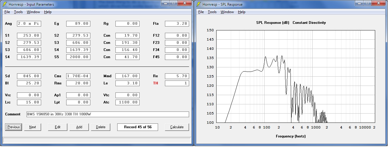
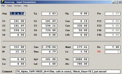
The same design modeled with my sub in it.
So -3db at 30 hz which is within the rules of this challenge. Much higher compression ratio, would be interesting to see if the driver stays intact. Could we make this box from 1 5x5 or 4x8 sheet plus a 2x4 sheet?
The question is asked in almost every TH thread that is started in here. Hey can you guys design this for 30/20/10hz? This will give us a chance to say sure! We can and this is how much output you are going to lose.
This box posted by ianb from post #61 of the 15" tapped horn with RCF thread is about a 3rd bigger than the SS15 volume wise and will do around 30hz. Considerably higher compression ratio though.
The same design modeled with my sub in it.
An externally hosted image should be here but it was not working when we last tested it.
So -3db at 30 hz which is within the rules of this challenge. Much higher compression ratio, would be interesting to see if the driver stays intact. Could we make this box from 1 5x5 or 4x8 sheet plus a 2x4 sheet?
Ah, so the problem is the sum of the width of the cuts and the sum of the path length to use a 15" driver? There just isn't enough wood. But there would be possibly for a 12"? Or a 10"?
How about if we changed the rules of the challenge and you can use any size driver? Just get the max output from 30hz-80/100hz you can out of a single sheet of plywood plus a 2x4 sheet for those that need it.
How about if we changed the rules of the challenge and you can use any size driver? Just get the max output from 30hz-80/100hz you can out of a single sheet of plywood plus a 2x4 sheet for those that need it.
I have several drivers laying around that we can experiment with. Choose whichever you prefer and I will build the box to do the comparison with.
Sundown SA-8 v.2
QTS .338
QMS 10.1
VAS 7.44 litres
QES .350
FS 34.6
RE 3.36
LE 1.34
BL 17.46
XMAX 16.5mm
DD 15.57
SD 190.3
Skar Audio VVX-10
QTS .416
QMS 4.320
VAS 24.5
QES .460
FS 26.67
RE 3.8
LE 3.09
BL 17.55
XMAX 21
DD 20.45
SD 328.5
Alpine SW10R-10D2
LE 3.04
FS 32hz
VAS 18L
QMS 7.05
QES .59
QTS .55
SD 333
XMAX 20mm
All of these drivers will take a ridiculous amount of abuse, have an extremely good cost to air displacement ratio and are available on the internet cheaply. The sundown looks promising to my rookie eyes. I would be willing to blow up any of these drivers for the sake of the experiment.
I had not understood your "Single Sheet" also included another 1/4 sheet,The question is how much amplitude are we giving up by staying with a cabinet that is SS15 size while tuning to 30-33hz?
Could we make this box from 1 5x5 or 4x8 sheet plus a 2x4 sheet?
a pair of Keystone subs can be made from approximately 2.5 sheets.
http://www.diyaudio.com/forums/subwoofers/185588-keystone-sub-using-18-15-12-inch-speakers.html
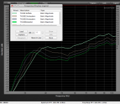
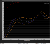
Although normally the Keystone F3 is about 36 Hz, I also tried it in various "Step Down" modes, covering more of the exit with a piece of plywood clamped in place each time.
The screenshots below show the response using a B&C18SW115-4 and twoo Lab 12", the 12" step down reduced the mouth to 15", 10" and 7 inch high.
This resulted in lower extension at the expense of upper response, an increase of 6 dB at 30 Hz cost 4-5 dB in the rest of the range above 40 Hz for the 18", and a more pronounced "scoop out" with the lower Fs Lab 12".
The upper loss is not worth the lower gain for any of the musical genres I normally work with, but the option to simply bolt on a plate and get a lower response is there if I ever needed more pants leg flapping with less chest punch😉.
Art
Attachments
Last edited:
Well I figured out that all of my other drivers on hand model horribly in a TH except the Alpine somewhat.
Thank you for the suggestion weltersys! I am going to read through those threads right now.
Thank you for the suggestion weltersys! I am going to read through those threads right now.
Well I really like the keystone sub and think I am going to build two of those for my DC audio drivers. However I am still determined to build a box similar in size to the SS15 but with 30 hz extension to finish the experiment of how much output loss there will be. To make it fair I am going to have to find a driver that models well in the SS15 box and a 215L 30 hz fold.
I am going to be running these full tilt for 6-8 hrs straight at an upcoming event so it will be interesting to see if the cones hold up. If they don't I will have my normal boxes there waiting.
So this also might answer some questions a lot of people have about whether drivers such as these will hold up at high pressure in a TH. This box has a fairly low compression ratio so though I am a newb, I think it will be fine. I will also most likely run my MFW-15 driver in these cabs until I experience a failure just to answer some of my own questions from threads predicting power handling in a tapped horn. It is a driver with well documented power handling and failure points in reflex and sealed enclosures. So it will make for a fun experiment.
Thanks for emailing me about your sub box - I'm a huge fan of trap and dubstep and this sounds like a cool project.
When it comes to making very small tapped horns, I've built a ton of 'em over the past few years. The big problem that I keep running into as I make the box very very small is that air leaks and flex become a huge issue.
Basically what happens is that the larger the horn is (compared to the cone size), the less that flex and leaks are screwing up your efficiency.
Conversely, if you make it small, flex and leaks can literally suck five or ten decibels of efficiency away on the low end.
If you look at the impedance curve of the finished tapped horn, you won't see the big deep null that you expect to see in a tapped horn. It's basically acting like something between a sealed box and a tapped horn.
One would think that the solution would be to simply be very very careful about sealing the tapped horn, but in my experience, that hasn't been sufficient. The box needs to be solid as granite. When you tap on the side walls it needs to sound like you're rapping your knuckles on a block of marble.
Luckily, I found a solution that works! (Yay!)
Basically, you build the tapped horn the way that B&W used to build their Matrix speakers. The loudspeaker box is a 'matrix' of wood. I tried using simple cross braces, and for very small tapped horns, it didn't cut it. For my subs, I needed to do a full-on Matrix of wood.

It's actually not as hard as it looks. Here's how I did it:
1) My sub was similar to Mike's Insubnia, pictured above
2) Normally, a tapped horn would have six sides. (a rectangular box.)
3) In my sub, instead of having a top and bottom sheet, there are four sheets. Does that make sense? So the wood pieces go "bottom sheet" -> "bottom middle sheet" -> "top middle sheet" -> "top sheet"
It's a LOT of cutting. But you can still use the same sub plans. My construction method doesn't change the horn path, it doesn't change the shape of the wood pieces. It basically just subdivides the horn into four pieces that are bonded together. And because they're bonded together the horn is uber solid. Just seriously inert.
An externally hosted image should be here but it was not working when we last tested it.
Same idea as cardboard furniture.
Last but not least 🙂
Some of the people reading this might think this is ridiculous overkill.
It's really not, because horns are very resonant. And their efficiency is due to resonant standing waves in the enclosure. I found this out the hard way when I built a ten hertz tapped horn a couple years back. You could actually run your hand across the box, and feel the areas of low and high pressure. (In a sealed cube, the pressure maximums are on the six sides; in a tapped horn, the pressure maximums are staggered all over the place, so there are spots of VERY high pressure, then a foot or two away there's almost no pressure at all!)
The problem with that high pressure is that any flex will just NUKE the efficiency of the box. Which really defeats the purpose of building a tapped horn in the first place. And the problem is exacerbated by the use of large high excursion woofers with four thousand watt amplifiers... Like the OP is doing.
This isn't to discourage the use of a tapped horn; I think this is a cool project! But don't even think about doing it unless you're able to do one of two things:
1) Make a matrix tapped horn using 1/2" plywood. (It would basically be equivalent to FOUR tapped horns, bonded together, with much much higher rigidity than a single TH using 1/2".)
OR
2) Make a conventional tapped horn out of something insanely beefy. Such as 1" plywood, or better yet, sheets of aluminum or a composite.
If you're good with composites that would help too. With four thousand watts and huge excursion, this enclosure will need to be strong enough to get hit by a car without flexing.
ahh.... back to flutes and clarinets.....
(I know at least one person will catch the reference....)
(I know at least one person will catch the reference....)
This isn't to discourage the use of a tapped horn; I think this is a cool project! But don't even think about doing it unless you're able to do one of two things:
1) Make a matrix tapped horn using 1/2" plywood. (It would basically be equivalent to FOUR tapped horns, bonded together, with much much higher rigidity than a single TH using 1/2".)
OR
2) Make a conventional tapped horn out of something insanely beefy. Such as 1" plywood, or better yet, sheets of aluminum or a composite.
A horn path coiled in three dimensions should also work. See The Subwoofer DIY Page v1.1 - Projects : A "Proof of Concept" tapped pipe** - introduction
That approach could be used for a path with constant cross-section, or constant expansion (by adjusting the position of the center panels).
ahh.... back to flutes and clarinets.....
(I know at least one person will catch the reference....)
Yup...
- Status
- Not open for further replies.
- Home
- Loudspeakers
- Subwoofers
- The flat to 30hz, Single Sheet (modified) challenge!