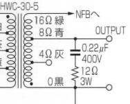
Hi, my output transformer burned out. I ordered a pair of new ones, but I have a problem with the connection. There are more cables from the new transformers. The black cable is ground? And the green one is? Feedback? If so, how should I connect it?


Not exactly on topic, but Fisher ran EL84s at crazy-high voltages. I don't know if modern EL84s will take that kind of abuse. You might want to increase the resistance, and wattage, of R86 and R87. This should lower the voltage on the EL84 screen grids as well, which would be no bad thing. Of course this might lower the voltage at C2A a bit too much so you'd need to adjust R84 to compensate.
I replaced the blown OPTs on two Fisher monos. A small network across the secondary, as shown in the attachment, can help protect the OPTs if a signal is present and a speaker is not connected.
S.
I replaced the blown OPTs on two Fisher monos. A small network across the secondary, as shown in the attachment, can help protect the OPTs if a signal is present and a speaker is not connected.
S.
Attachments

Unless I'm missing something, that bias setup on the schematic is wrong.Not clear which way to wire the primary. The colors are different.
The earth wire is a shield, and should be grounded to the chassis.
Otherwise follow the attached schematic. The secondary colors are also different.
Feeding non-rectified AC to the filaments of the input tubes, and using a center tap to feed bias voltage?
Where's the DC bias rectifier at?
I replaced the blown OPTs on two Fisher monos. A small network across the secondary, as shown in the attachment, can help protect the OPTs if a signal is present and a speaker is not connected.
An even higher power rating on the 12 ohm resistor is good.
No need for those to fail, and then the OTs fail.
Not exactly on topic, but Fisher ran EL84s at crazy-high voltages. I don't know if modern EL84s will take that kind of abuse. You might want to increase the resistance, and wattage, of R86 and R87. This should lower the voltage on the EL84 screen grids as well, which would be no bad thing. Of course this might lower the voltage at C2A a bit too much so you'd need to adjust R84 to compensate.
Ehh! Did you actually look at the schematic? Only 320Vdc across the EL84 tubes from plate to cathode. No crazy-high here due to the cathode current being used to heat the small tubes.
Very unusual grid bias circuit, with attenuated positive DC voltage from the output tube cathode biasing resistor.
Unless I'm missing something, that bias setup on the schematic is wrong.
Feeding non-rectified AC to the filaments of the input tubes, and using a center tap to feed bias voltage?
Where's the DC bias rectifier at?
There's no negative bias supply. The tube filaments in series raise the output tube cathodes to 40VDC. Then a small portion of that positive bias is applied to the grids to "fix" the grids in relationship to the cathodes. It's kind of like the old Williamson biasing method, where the output tube grids are "biased" with a portion of the positive cathode voltage. At least that's what it looks like to me.
Last edited:
Hi, my output transformer burned out. I ordered a pair of new ones, but I have a problem with the connection. There are more cables from the new transformers. The black cable is ground? And the green one is? Feedback? If so, how should I connect it?View attachment 1167245View attachment 1167246
First of all, are these actual copies of Fisher output transformers, as opposed to generic replacements? I ask because if they are not exact copies of the originals, you're likely to have some stability issues with the amplifier and would need an oscilloscope to test for any problems they might cause.
Assuming they are copies made by someone who used the Fisher OPTs as a template, then you would connect the feedback to the 16 ohm taps as in the schematic. The fact that the color-coding is different from the schematic, and that the 4 ohm (?) tap is labelled "FB," makes me concerned that they were perhaps intended for a different amp.
You're also going to have to experiment with the orientation of the primaries. If the amp starts to howl as it warms up then you will need to reverse the primary leads to the ouput tubes.
Ehh! Did you actually look at the schematic? Only 320Vdc across the EL84 tubes from plate to cathode. No crazy-high here due to the cathode current being used to heat the small tubes.
If I read the schematic correctly, it's 380 minus 40= 340 volts. Though 340 is not crazy high, with todays, at times, high-ish line voltages, the B+ feeding the OPTs could approach 400 volts. With the new tube supply situation as it currently stands, prudent voltages are the way to go, IMHO. A few wirewound resistors are less expensive than even one EL84.
S.
Those ERO grid coupling caps are famously leaky these many years later. Might have contributed to your OPT failure, and should be replaced prophylactically.
All good fortune,
Chris
All good fortune,
Chris
Note that the amp was NOT designed for EL84's....... but 7189's.... which are much higher B+ tubes.If I read the schematic correctly, it's 380 minus 40= 340 volts. Though 340 is not crazy high, with todays, at times, high-ish line voltages, the B+ feeding the OPTs could approach 400 volts. With the new tube supply situation as it currently stands, prudent voltages are the way to go, IMHO. A few wirewound resistors are less expensive than even one EL84.
S.
No, because the color codes are different and are not defined.
There are no phase dots on the label, so contact the factory.
There are no phase dots on the label, so contact the factory.
Are you able to tell me which color cable to connect to what? 🙁
I can suggest connections, but unless the transformers are a direct copy of the Fishers I would be concerned about damaging the amp and your speakers. Once again I have to ask, where did you get them?
Also, as others have suggested, if the amp blew an output transformer, it probably has some other serious problems. Was the amp in this condition when you got it? Did this happen while you were using it? Have the power supply and coupling capacitors been replaced with new ones?
With a complex feedback amplifier like the Fisher, you cannot simply drop in any old output transformer. And when an output transformer fails, there's usually a reason. It rare for Fisher output transformers to just fail on their own.
Description from the manufacturer's website:
For use in a high performance valve amplifier, where high output level and exceptional bandwidth are required. Designed for use with Push-Pull output stage or an AC coupled cathode follower or SRPP circuit driving a nominal 4Ω, 8Ω, and 16Ω speakers. Dedicated to the EL84 power amplifiers. Ungapped.
Impedance: 8k:4Ω, 8k:8Ω, or 8k:16Ω
Wattage: 45W
Cathode feedback: No
Winding Configuration: Interleave Winding
Frequency response @50Ω source, 600Ω load: +/- 0.5 dB 14 Hz to 80 kHz (Ap)
Max primary DC per side: 60mA
Primary Inductance: 100H @100Hz
Secondary Inductance: 200/400/700mH @100Hz
Total DC Resistance PRI: 340Ω
Total DC Resistance SEC: 1Ω
THD+Noise: <0.1% @ 1K Hz
Core Size: EI86, stock 42mm, Z11 Grain Oriented lamination steel. Ungapped.
Bell-style package.
Weight: 2kg
*I have already written to the manufacturer to describe the cables to me.
* The capacitors are defective, so I have already ordered new ones.
Description from the manufacturer's website:
For use in a high performance valve amplifier, where high output level and exceptional bandwidth are required. Designed for use with Push-Pull output stage or an AC coupled cathode follower or SRPP circuit driving a nominal 4Ω, 8Ω, and 16Ω speakers. Dedicated to the EL84 power amplifiers. Ungapped.
Impedance: 8k:4Ω, 8k:8Ω, or 8k:16Ω
Wattage: 45W
Cathode feedback: No
Winding Configuration: Interleave Winding
Frequency response @50Ω source, 600Ω load: +/- 0.5 dB 14 Hz to 80 kHz (Ap)
Max primary DC per side: 60mA
Primary Inductance: 100H @100Hz
Secondary Inductance: 200/400/700mH @100Hz
Total DC Resistance PRI: 340Ω
Total DC Resistance SEC: 1Ω
THD+Noise: <0.1% @ 1K Hz
Core Size: EI86, stock 42mm, Z11 Grain Oriented lamination steel. Ungapped.
Bell-style package.
Weight: 2kg
*I have already written to the manufacturer to describe the cables to me.
* The capacitors are defective, so I have already ordered new ones.
Okay, that helps. They seem like well-made transformers. But they are not exact copies of the originals. You can try them. Connect the output taps as in the Fisher (4 ohms would be the green lead), with the feedback attached to the 16 ohm tap. For the primaries, there's no way of knowing which orientation is correct. If the blue and yellow leads are out of phase, the amp will begin to howl as it warms up, because you now have positive instead of negative feedback. The solution is to reverse the blue and yellow leads to the output tube plates.
But there still remains the problem of amplifier stability. Feedback amplifiers are tuned specifically to the output transformers. You might get low-frequency motorboating, and/or high frequency oscillation. If you don't have an oscilloscope or the experience to adjust the feedback compensation circuitry, there's a fair chance you might damage your speakers.
OTOH, it they might work fine, but without a 'scope to check the output of the amp, there's no way to know if the amp is functioning properly, and that poses a serious risk to your speakers.
I'm sorry there isn't a better answer. It's possible to replace the transformers in vintage amps with modern substitutes, but only if you have experience testing an amplifier with a scope and making the necessary changes to the circuit to compensate for the new transformer.
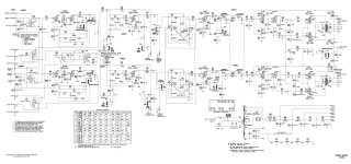
Fisher X-100 full schematic.

Curiously, the X-100's power amp section has a striking family resemblance to the pure power amp SA-100, which is a fixed bias design.

Curiously, the X-100's power amp section has a striking family resemblance to the pure power amp SA-100, which is a fixed bias design.
Attachments
Last edited:
- Home
- Amplifiers
- Tubes / Valves
- The Fisher X100A New Output Transformer