Hello Sy,
 Now I think I've got the picture, please correct me if I'm wrong...the device has a initial high resistance (relatively), acting as a current limiter, as it heats up the resistance drops, allowing the full current. So by putting them on the HV secondary, you get a simple soft start.
Casey
NTC (negative temperature coefficient) resistors.
Now I think I've got the picture, please correct me if I'm wrong...the device has a initial high resistance (relatively), acting as a current limiter, as it heats up the resistance drops, allowing the full current. So by putting them on the HV secondary, you get a simple soft start.Casey
Now I think I've got the picture, please correct me if I'm wrong...the device has a initial high resistance (relatively), acting as a current limiter, as it heats up the resistance drops, allowing the full current. So by putting them on the HV secondary, you get a simple soft start.
BINGO! Mouser Catalog Page for NTC Devices
Check out Jim McShane. You might get a better deal from him after shipping charges are factored in. BTW, Jim is 1 of the straightest shooters you'll ever get to know. He doesn't deal in BS.
Eli,
I must have had a pretty nasty episode of “cerebral flatulence”, based on the blank I was pulling with this subject. I have seen NTC’s used in bias circuits on old amps, I just didn’t make the connection earlier.
Tom Bavis said,
After reading the specs. of the various NTC offerings, this seems like good advice.
When looking at NTC specs, is the resistance given the minimum (i.e, hot),or the maximum ?
Casey
BINGO! Mouser Catalog Page for NTC Devices
I must have had a pretty nasty episode of “cerebral flatulence”, based on the blank I was pulling with this subject. I have seen NTC’s used in bias circuits on old amps, I just didn’t make the connection earlier.
Tom Bavis said,
Install an inrush limiter (Keystone CL-70 or similar) in the primary and reduce the line fuse to 2.5A slo-blo.
After reading the specs. of the various NTC offerings, this seems like good advice.
When looking at NTC specs, is the resistance given the minimum (i.e, hot),or the maximum ?
Casey
Casey,
The ideal PSU sequence is bias 1st, heaters 2nd, and B+ last. The ideal sequence is not possible with a single power trafo. Anything that slows the bias rise down is (IMO) bad. That's why I like the NTC parts on the B+ winding. There is enough of a delay in B+ rise that the bias supply can electrostatically shield the warming cathodes against stripping. Also, the biggest turn on surge is the B+ into the near dead short of the uncharged filter caps. Inrush limiting the B+, and only the B+, prevents cathode stripping and power trafo clang.
I'm not sure about the cold and hot resistances of the various inrush current limiter types. I'll touch base with Jim McShane and then post accurate info.
It Lives!!!
I received my “cold war” capacitor order Friday, and decided to go ahead and see if I could get the Fisher working without any mods (except coupling caps) to get a bead on its overall health…to say that I’m glad I did is a huge understatement.
First thing on the agenda was to repair the volume control , the right channel was dangerously noisy. I looked high and low for a drop in replacement to no avail. I did however run into a little faq during my search on vintage pot repair (can’t remember where) that suggested using a No. 2 graphite pencil to coat the worn element…hmmm.
I broke down the pot and discovered the right channel resistive track had a nice groove worn into it , the left side had some pretty good wear as well. After cleaning all the parts, I scribbled a even coat of pencil over both elements, and smeared it around with my finger. I re-assemble the pot and put it back in. I wouldn’t know if it worked until I re-capped the amp, and repaired the bias circuit, so I kept my fingers crossed.
Boy did it ever work !!! I was hoping for a moderately scratchy, but usable pot until I could replace it. I ended up with a dead quiet evenly tracking pot…amazing. Time will tell how long it lasts, but for now I know my volume control isn’t the weak link.
Next up was the coupling caps. I had read here, and elsewhere, how good the Russian military PIO caps were, so I ordered a bunch as well as a box of “consumer” Russian caps that the seller believed were NOS wax jobs from the fifties..they were cheap and I figured what the hell.
First the military caps. I didn’t realize at the time that there were steel cased PIO as well as the “good” ones…I bought the steel cased ones. At first I was bummed, then I decided to see if I could get the capacitor proper out of its steel prison. After roaching a couple I developed a cutting technique that worked without hurting the cap. After getting the caps out of their cases, I dipped them in Plasti-Coat, the stuff that you use to put rubber grips on pliers. As the stuff dries, it shrinks, wrapping the cap in a tight coat of rubber.
I then cut open one of the “wax” caps…I had a very pleasant surprise. They weren’t wax, they were PIO with a virtually identical build as the military version, I gave these the rubber treatment as well.
So I rebuilt the bias supply with a garden variety silicon bridge and electrolytic caps, and replaced all the coupling caps from the tape monitor in to the output tubes, checked the voltages and set it up in the shop…much joy ensued.
Right out of the gate it sounded good..very good. After a couple hours of spinning cd’s, the caps smoothed out, at first there was a slight upper-mid edge, but this is rapidly disappearing as the caps burn in. These caps are very good. I don’t have a selection of other caps to compare them too, but I can’t hear any problems with them.
After a couple hours of listening, my wife came home. I put her on the stool and played some cuts from the Fleetwood Mac “Rumors” CD. I watched as a smile slowly crossed her face as she listened. She turned to me and said “Your bringing this into the house, right?”. I had intended to just check out its condition, instead, my wife, my son, and myself listened for to it for 6 hours straight in its temporary spot in the living room.
I think they approve.
Casey
Five Pound Of S*** In A 3 Pound Bag
After being pleased with the Fisher so far, I decided to go ahead and see if I could kick it up a notch with the parts I have on hand (a large assortment of Ruskie caps and Plasti-Dip). Listening to a basically stock amp has brought me to the conclusion that anything beyond some basic refinement of this piece, and my efforts would be better spent building a different amp all together. It's just darn good as-is.
So, after staring at the schematic and layout, I went to work...
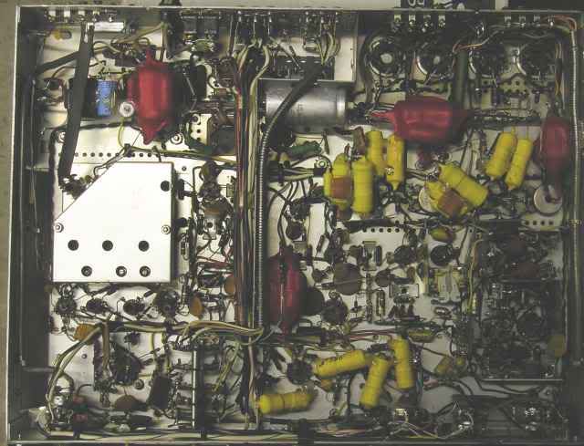
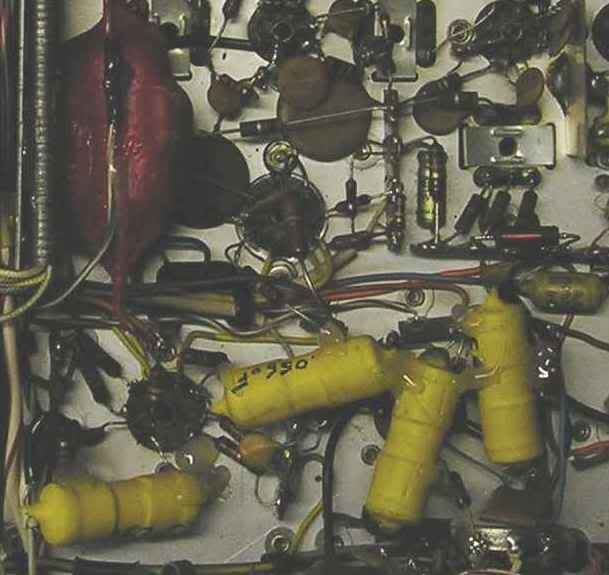
...I color coded thecaps yellow for signal, and red for power. Zooming in on the power amp I did the following...

...the untreated cap, laying horizontally to the left, is a 100uF/450V unit across the B+ connected directly to the OPT's center taps. The red "blobs" in the center and to the right are composite bypass caps made up of 1uF, .1uF PIO, and a .01uF silver/mica, the center one is paralleled with the 100uF cap, and the one to the right is connected to the screens. First I "de-nude" the PIO's and put 2 coats of Plasti-Dip on them individually, then I solder all three caps, and put 2 more coats on the assembly. This does three things. First it provides a air-tight seal to prevent the caps from absorbing moistere ( the bane of paper caps), second it puts a high voltage insulation on the caps (very important in tight fits like this), and third, it makes a very acoutically dead assembly to minimize/eliminate microphonics.
The yellow paralleled caps in the center are the cathode bypass caps. Again I used a 1uF,.1uF, and a .01uf in parrallel with the 50uF electrolyitic. They're not all gooped together because the 1uF and 50uF were done in the first go round, otherwise I would have. The remaining yellow caps are .05uF coupling caps. After installing the caps so that they didn't cover any vent holes, or get too close to hot power resistors, I shored them up by tacking the components together with hot-glue.
The other mods to the power section included installing 10 ohm/.25 watt resistors on the cathodes (providing a point to check bias, and fusable links),replacing the 330k grid bias resistors with 280k (560k's in parallel) to prevent bias creep with the EH 7591's, and changing the feedback connection on the OPT's from the 16 ohm tap to the 8 ohm tap. I changed the values of the feedback components from 2.2k/1000pF to 1.5K/1400pF (thanks Sy) to maintain the same feedback/time constant as stock.
Heres the bias mods...
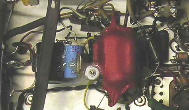
...I replaced the selenium bridge with a silicon one (a schottky will be next), the leaking dual 1000uF cap with a 2200uF/1000uF combo, the .1uF cap with another 1/.1/.01 combo, and the 5.6K/15K fixed voltage divider with a 3k/4.7k sealed pot/12k string. Voila, adjustable bias.
The line stage...
...I changed the coupling caps with treated PIO's and silver/micas, added another power supply bypass "blob" to the plate resistors, and re-purposed the "Low Filter" switch as a tone bypass switch. In the off position, the switch shunts the input to output of the tone circuitry, removing the tone components from the signal path. In addition to cleaning the signal, this gives me a little more gain (eliminates insertion loss) allowing me to use the "Tape Monitor" (one less stage) with my Swenson modded Toshiba 3950.
After all this I checked my voltages, and found that they were indeed higher than published (based on a nominal 110v line). I could live with that EXCEPT for the fact that my TFK smooth plates were running 14V on the filaments. Pondering what to do, I remembered the the cheap Chinese Variac I was given because of the pitted track making it unusable for bringing equipment up slow, the voltage bounced all over the place when you turned it up. I broke it down, pulled off the wiper, measured the track to find the winding that provided 110v, and soldered directly to this point. Now I have a 10 amp 120-110 transformer, and a convienient place to turn it on (toasted oem power switch).
Currently the weak link in my system IS NOT my amp 😀
When I think of the layout, the ferrous chassis and the low tube pedigree's, I suffer cognitive dissonance trying to square that with what I'm hearing...I just won't think about it and immerse myself into the incredible lush and detailed sound.
When I get the parts to repair the tuner section, I'll go back in and see if I can find any more simple tweeks, but if I can't, I will still be happy....for now😉
Casey
P.S. Eli, email me...My HD crashed and I lost your email addy.
After being pleased with the Fisher so far, I decided to go ahead and see if I could kick it up a notch with the parts I have on hand (a large assortment of Ruskie caps and Plasti-Dip). Listening to a basically stock amp has brought me to the conclusion that anything beyond some basic refinement of this piece, and my efforts would be better spent building a different amp all together. It's just darn good as-is.
So, after staring at the schematic and layout, I went to work...
...I color coded thecaps yellow for signal, and red for power. Zooming in on the power amp I did the following...
...the untreated cap, laying horizontally to the left, is a 100uF/450V unit across the B+ connected directly to the OPT's center taps. The red "blobs" in the center and to the right are composite bypass caps made up of 1uF, .1uF PIO, and a .01uF silver/mica, the center one is paralleled with the 100uF cap, and the one to the right is connected to the screens. First I "de-nude" the PIO's and put 2 coats of Plasti-Dip on them individually, then I solder all three caps, and put 2 more coats on the assembly. This does three things. First it provides a air-tight seal to prevent the caps from absorbing moistere ( the bane of paper caps), second it puts a high voltage insulation on the caps (very important in tight fits like this), and third, it makes a very acoutically dead assembly to minimize/eliminate microphonics.
The yellow paralleled caps in the center are the cathode bypass caps. Again I used a 1uF,.1uF, and a .01uf in parrallel with the 50uF electrolyitic. They're not all gooped together because the 1uF and 50uF were done in the first go round, otherwise I would have. The remaining yellow caps are .05uF coupling caps. After installing the caps so that they didn't cover any vent holes, or get too close to hot power resistors, I shored them up by tacking the components together with hot-glue.
The other mods to the power section included installing 10 ohm/.25 watt resistors on the cathodes (providing a point to check bias, and fusable links),replacing the 330k grid bias resistors with 280k (560k's in parallel) to prevent bias creep with the EH 7591's, and changing the feedback connection on the OPT's from the 16 ohm tap to the 8 ohm tap. I changed the values of the feedback components from 2.2k/1000pF to 1.5K/1400pF (thanks Sy) to maintain the same feedback/time constant as stock.
Heres the bias mods...
...I replaced the selenium bridge with a silicon one (a schottky will be next), the leaking dual 1000uF cap with a 2200uF/1000uF combo, the .1uF cap with another 1/.1/.01 combo, and the 5.6K/15K fixed voltage divider with a 3k/4.7k sealed pot/12k string. Voila, adjustable bias.
The line stage...
...I changed the coupling caps with treated PIO's and silver/micas, added another power supply bypass "blob" to the plate resistors, and re-purposed the "Low Filter" switch as a tone bypass switch. In the off position, the switch shunts the input to output of the tone circuitry, removing the tone components from the signal path. In addition to cleaning the signal, this gives me a little more gain (eliminates insertion loss) allowing me to use the "Tape Monitor" (one less stage) with my Swenson modded Toshiba 3950.
After all this I checked my voltages, and found that they were indeed higher than published (based on a nominal 110v line). I could live with that EXCEPT for the fact that my TFK smooth plates were running 14V on the filaments. Pondering what to do, I remembered the the cheap Chinese Variac I was given because of the pitted track making it unusable for bringing equipment up slow, the voltage bounced all over the place when you turned it up. I broke it down, pulled off the wiper, measured the track to find the winding that provided 110v, and soldered directly to this point. Now I have a 10 amp 120-110 transformer, and a convienient place to turn it on (toasted oem power switch).
Currently the weak link in my system IS NOT my amp 😀
When I think of the layout, the ferrous chassis and the low tube pedigree's, I suffer cognitive dissonance trying to square that with what I'm hearing...I just won't think about it and immerse myself into the incredible lush and detailed sound.
When I get the parts to repair the tuner section, I'll go back in and see if I can find any more simple tweeks, but if I can't, I will still be happy....for now😉
Casey
P.S. Eli, email me...My HD crashed and I lost your email addy.
Casey,
Duke Ellington had it nailed. "If it sounds good, it is good".
It's NOT an accident that Avery Fisher got very rich selling NICE electronics.
EMail sent.
Eli D.
Duke Ellington had it nailed. "If it sounds good, it is good".
It's NOT an accident that Avery Fisher got very rich selling NICE electronics.
EMail sent.
Eli D.
Casey,
If that variac gives you trouble down the line, put RCA 7058s in the unit as replacements for the TFK ECC83s. The 7058 is rated to produce correct emission with anything between 12 and 14 V. on the heater. The mobile versions of "standard" tubes have their uses. 😉 Top to bottom tonal balance in RCA 'X7s is HARD to beat.
BTW, Fisher, Dyna, etc. used TFK not because they sound better than RCA, but because they worked well and cost less. Back in those days, Mullard was the premium brand. Remember, these were for profit enterprises.
Hi Eli,
Good to know. I don't think I'll be having any trouble with the variac though, it actually has very little time on it. The cruddy QC during construction left the winding uneven where the "brush" contacted it, leading to arcing that quickly ruined the contact surface. Not an issue with my soldered connection. It's a biggie rated at 10 amps, it should live happily and long feeding my 2ish amp draw Fisher.
True, these companies were controled by the bean counters. But you have to remember it was less than 20 yrs after WW II, and the German economy was still weakened, the US dollar was way stronger than the DM. Hence, you could buy better quality for less money...win-win.
I am willing to accept that a part of the TFK legend is just that...legend. But right now, with the exception of the output tubes, I am not willing to change squat on the 'ol 800C. In fact, I've pulled the 2 TFK's in the unused phono section so that I would have spares for the rest of the amp.
The biggest bummer with these forums is the inability for us to actually hear other peoples gear. We are left trying to convey the sound with words...it don't work. That said, I will just say that my receiver in its current state does everything I think it should..unbelievable bass (for any amp in its power class), liquid midrange, silky detailed highs. I'm not under the illusion that it's the "be all" amp if such a thing exists, nor I'm I saying it will be my last. I am saying that I have not enjojed listening to music this much in years...and that is what it's about...however you get there.
Casey
If that variac gives you trouble down the line, put RCA 7058s in the unit as replacements for the TFK ECC83s.
Good to know. I don't think I'll be having any trouble with the variac though, it actually has very little time on it. The cruddy QC during construction left the winding uneven where the "brush" contacted it, leading to arcing that quickly ruined the contact surface. Not an issue with my soldered connection. It's a biggie rated at 10 amps, it should live happily and long feeding my 2ish amp draw Fisher.
BTW, Fisher, Dyna, etc. used TFK not because they sound better than RCA, but because they worked well and cost less. Back in those days, Mullard was the premium brand. Remember, these were for profit enterprises.
True, these companies were controled by the bean counters. But you have to remember it was less than 20 yrs after WW II, and the German economy was still weakened, the US dollar was way stronger than the DM. Hence, you could buy better quality for less money...win-win.
I am willing to accept that a part of the TFK legend is just that...legend. But right now, with the exception of the output tubes, I am not willing to change squat on the 'ol 800C. In fact, I've pulled the 2 TFK's in the unused phono section so that I would have spares for the rest of the amp.
The biggest bummer with these forums is the inability for us to actually hear other peoples gear. We are left trying to convey the sound with words...it don't work. That said, I will just say that my receiver in its current state does everything I think it should..unbelievable bass (for any amp in its power class), liquid midrange, silky detailed highs. I'm not under the illusion that it's the "be all" amp if such a thing exists, nor I'm I saying it will be my last. I am saying that I have not enjojed listening to music this much in years...and that is what it's about...however you get there.
Casey
Sy,
Sorry about that...forgot where I was there for a moment...won't happen again
My apologies for the extra work,
Casey
Sorry about that...forgot where I was there for a moment...won't happen again
My apologies for the extra work,
Casey
Well, never one to leave well enough alone, I reviewed my fisher schematic to see if I could squeeze a little more gain out of the line stage. My Swenson modded Toshiba 3950 didn't have enough drive to push the amp to clipping, so depending on the CD, it didn't always have enough drive.
This is when I discovered my "oopsy" 🙁 , I hadn't really removed the tone completely from the circuit...It was still in parallel with the 2nd stage input. Believe it or not, I had never actually turned the bass/treble controls after the last mod...DUH!! Sure enough, they were still partially active.
So back in I went, and this time I simply wired around the circuit,as well as replacing the high cut filter with a resistor. I figured it was time to remove all the "bandaids" in the form of small caps in parallel with various resistors. Surely they were there to correct the FR abberations caused by the various filters. I reassembled, and checked it out....it sounded like poo .
.
I then went back to my LtSpice sims to see if I could suse this out. I found that they all (tone/filters/correction) worked in intimate concert to give a reasonably (not great) flat response. In addition, the high cut filter was effectively a 200k grid snubber . I think I discovered the reason behind the 500C/800C's weak HF extension, -3dB @ 20k.
Having not used the tone/filters once since getting the 'ol girl online, I figure I wouldn't miss 'em. So I set out to redesign the line stage, trying to keep the good and chucking the bad. I have mistakenly stated that the line stage had 30+ dB gain in an earlier post. I had missed the ground connection to the tone stack in my earlier sim. With it, the two 'AX7 stages plus tone stack has a gain of around 16dB..this would be my goal with a single stage.
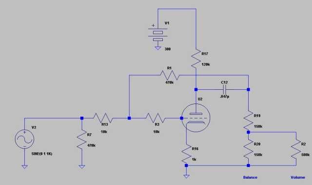
This is the sim schematic of the stock Fisher line stage...
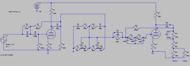
...and this is my new design...
😀 😀 😀
Less is definately more. I have retained the 16dB of gain, and the sim'ed FFT's are virtually identical...the FR perfomance however is not. It sims out to beyond 200k.
Everything has improved dramatically..attack, extension, detail, ect,ect.
Yee Freakin' Ha !!!
Casey
This is when I discovered my "oopsy" 🙁 , I hadn't really removed the tone completely from the circuit...It was still in parallel with the 2nd stage input. Believe it or not, I had never actually turned the bass/treble controls after the last mod...DUH!! Sure enough, they were still partially active.
So back in I went, and this time I simply wired around the circuit,as well as replacing the high cut filter with a resistor. I figured it was time to remove all the "bandaids" in the form of small caps in parallel with various resistors. Surely they were there to correct the FR abberations caused by the various filters. I reassembled, and checked it out....it sounded like poo
.I then went back to my LtSpice sims to see if I could suse this out. I found that they all (tone/filters/correction) worked in intimate concert to give a reasonably (not great) flat response. In addition, the high cut filter was effectively a 200k grid snubber
. I think I discovered the reason behind the 500C/800C's weak HF extension, -3dB @ 20k.Having not used the tone/filters once since getting the 'ol girl online, I figure I wouldn't miss 'em. So I set out to redesign the line stage, trying to keep the good and chucking the bad. I have mistakenly stated that the line stage had 30+ dB gain in an earlier post. I had missed the ground connection to the tone stack in my earlier sim. With it, the two 'AX7 stages plus tone stack has a gain of around 16dB..this would be my goal with a single stage.
This is the sim schematic of the stock Fisher line stage...
...and this is my new design...
😀 😀 😀
Less is definately more. I have retained the 16dB of gain, and the sim'ed FFT's are virtually identical...the FR perfomance however is not. It sims out to beyond 200k.
Everything has improved dramatically..attack, extension, detail, ect,ect.
Yee Freakin' Ha !!!
Casey


SY said:You can find examples of the sort of input stage I'm talking about in Morgan Jones's "Valve Amplifiers." Check out the Bevois Valley project- that input stage could work very well in this application. While you're perusing that book, look up the Maida regulator circuit- that would be perfect for the screen supply.
I'm only on page 1 of this thread, but it sure looks to me like this amp already has a direct-coupled voltage amp into a split-load invertor (aka concertina) or am i missing something?
Chris & i are working on a PP amp.... when i gave him the vintage Scott amp he started researching and made some noise restoring it. What's the point, a pretty amp that doesn't reach its potential, and will sit and collect dust... so we stripped it down to the iron and some of the sockets. No regrets.
dave
valveitude said:RCA definitely WOULD be the most pragmatic solution.
Chris has an RCA phono & it works fine.
dave
planet10 said:
I'm only on page 1 of this thread, but it sure looks to me like this amp already has a direct-coupled voltage amp into a split-load invertor (aka concertina) or am i missing something?
No, you're not missing anything- that's a classic topology, but the 12AX7 is a very suboptimal choice. Mu is high, gm is low, current is very low, so there's a lot of Millering at the input, the phase splitter is enormously sensitive to the transition from class A, and it is marginal for driving the capacitance of the output tubes.
MJ used ECC88, I prefer 12AT7.
edit: Ignore last comment on 12AX7- the output stage is pentode, which reduces its capacitance.
Hi planet10,
Depending on the unit, this is can be a valid approach. This piece however has a certain aural magic bone stock. I wanted to sneek up on any changes to it for a few reasons. First, I had nothing else to listen to when I purchased it, and getting it online stock gave me some instant gratification, second, It's been a good learning experience seeing what improves it and what doesn't to my ear, and third, the 800C has a fair amount of resale value, so I kept all the little bits I pulled ,and made sure that everything is reversable.
I may go this route as a temp solution. I've already done more to the pre section than I intended (I believe it was Sy that said there is no such thing as a "classic" pre, I agree...now). The Fisher is intended as a "stop-gap" (though at this point, a mighty fine one) until I build the rest of my system. Utimately, it will serve as a tuner. My planned electronic progression is as follows. First, a stand alone phono pre (Thorstens tube "El Cheapo"), second, a line amp/source selector (CCS 12B4), and finally a new power amp with better iron, and all the improvements a "ground floor" approach can bring.
Sy,
I yield to your judgement here, BUT , doesn't the cream puff load of the 7591's make these points mute, or at least minimize the negatives? I realize Fisher used the AX7 basically because he could, rather than it being the shiz-nitty tube of choice, but did he truly compomise his amp doing so ?
Casey
Chris & i are working on a PP amp.... when i gave him the vintage Scott amp he started researching and made some noise restoring it. What's the point, a pretty amp that doesn't reach its potential, and will sit and collect dust... so we stripped it down to the iron and some of the sockets. No regrets.
Depending on the unit, this is can be a valid approach. This piece however has a certain aural magic bone stock. I wanted to sneek up on any changes to it for a few reasons. First, I had nothing else to listen to when I purchased it, and getting it online stock gave me some instant gratification, second, It's been a good learning experience seeing what improves it and what doesn't to my ear, and third, the 800C has a fair amount of resale value, so I kept all the little bits I pulled ,and made sure that everything is reversable.
Chris has an RCA phono & it works fine.
I may go this route as a temp solution. I've already done more to the pre section than I intended (I believe it was Sy that said there is no such thing as a "classic" pre, I agree...now). The Fisher is intended as a "stop-gap" (though at this point, a mighty fine one) until I build the rest of my system. Utimately, it will serve as a tuner. My planned electronic progression is as follows. First, a stand alone phono pre (Thorstens tube "El Cheapo"), second, a line amp/source selector (CCS 12B4), and finally a new power amp with better iron, and all the improvements a "ground floor" approach can bring.
Sy,
the 12AX7 is a very suboptimal choice. Mu is high, gm is low, current is very low, so there's a lot of Millering at the input, the phase splitter is enormously sensitive to the transition from class A, and it is marginal for driving the capacitance of the output tubes.
Ignore last comment on 12AX7- the output stage is pentode, which reduces its capacitance.
I yield to your judgement here, BUT , doesn't the cream puff load of the 7591's make these points mute, or at least minimize the negatives? I realize Fisher used the AX7 basically because he could, rather than it being the shiz-nitty tube of choice, but did he truly compomise his amp doing so ?
Casey
As I said in the edit, the capacitance issue is moot. But the Millering and lower linearity of 12AX7 at the large swings necessary for the voltage amplifier make it a less optimal choice than ECC88 or 12AT7. Clearly it works OK, but it's not the best, and if you're going to optimize things...
12AX7 was a safe choice in 1950-whatever, but we can do better today, especially because this isn't a production unit.
12AX7 was a safe choice in 1950-whatever, but we can do better today, especially because this isn't a production unit.
Sy,
Admitedly I'm still nursing my first cup of coffee here, and not firing on all 8 cylinders, but what besides the input capacitance does the "Millering" effect ? The linearity issue is another story. Since I've already sliced off a considerable chunk of the "sacred cow" with the line stage, I'm not as queasy about diddling with the PA. I have some dandy ECC88 variants on hand, but I am concerned with the extra B+ load. As it stands, the tranny doesn't get hot (well, not so hot that you can't hold on to it),but upping the current draw 10 fold (approx. 1ma to 10ma) in the VA/Splitter stage gives me pause. I guess I'll have to do some power budgeting, and see if it's feasible.
Casey
Eh, if you're powering up an output stage, you've got a few milliamps to spare.
The Millering is an issue because of the large value of the volume control. You'll find that frequency response changes with volume setting.
The Millering is an issue because of the large value of the volume control. You'll find that frequency response changes with volume setting.
- Status
- Not open for further replies.
- Home
- Amplifiers
- Tubes / Valves
- The Fisher 500C/800C Challenge (long..dialup warning)