
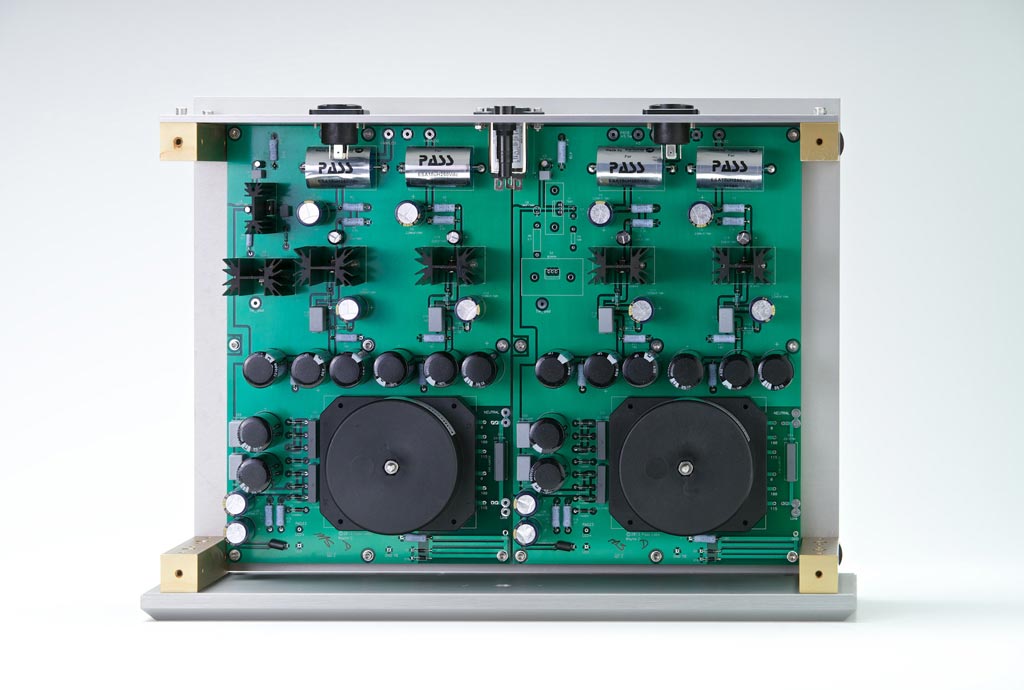
I don't see Banks Of Redundantly Parallel diodes in power supply.
Superman from Down Under ?
your x-ray sight ...... so no (possible) diodes dOWN uNDER ?

Certainly a possibility but I don't think so.
An externally hosted image should be here but it was not working when we last tested it.
well , one thing is sure - Pa didn't wrote those lines
besides - you (and Mighty Moi) certainly are not in group targeted , to read those lines

besides - you (and Mighty Moi) certainly are not in group targeted , to read those lines
well , one thing is sure - Pa didn't wrote those lines
besides - you (and Mighty Moi) certainly are not in group targeted , to read those lines
Hehehehe
well , one thing is sure - Pa didn't wrote those lines
besides - you (and Mighty Moi) certainly are not in group targeted , to read those lines
Sorry Zen Mod forgive my dumbness. I just realised that was the Xs PREAMP Power supply, NOT the POWER Amp power supply

Ok this is going to be the output stage of the balanced circuit. The exact sought of distortion I am after, and an improvement over the other one.
So I'm going to do super symmetry on the first 2 stages going for minimum distortion in those stages then connected to this out put stage which will work outside of the feedback loop.
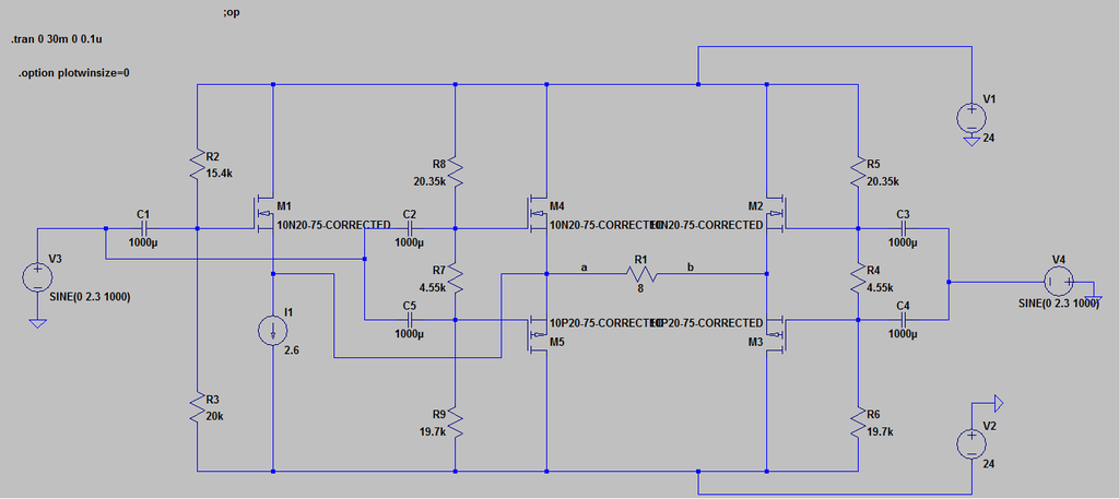
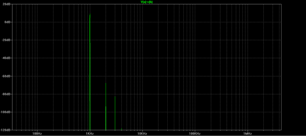
So I'm going to do super symmetry on the first 2 stages going for minimum distortion in those stages then connected to this out put stage which will work outside of the feedback loop.
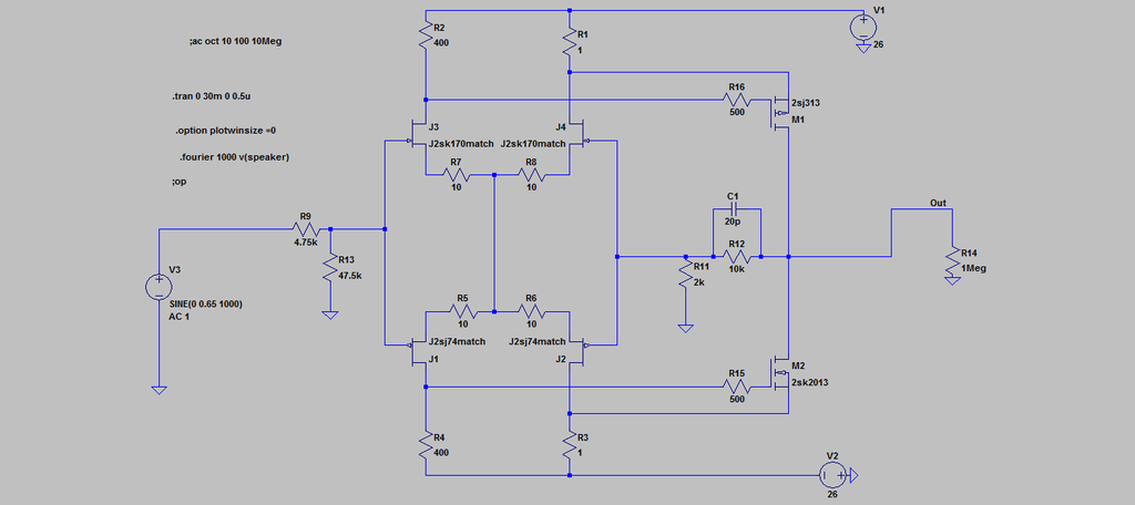
you're going backwards , and exploring bush beaten to death
take already drawn circuit , it'll work as is , with optimization of resistor values and exact type of mosfets
then you can add , if you wish to go that way , CCS at outputs
I mean - if you're interested in that symm. circuit at all .....
if not , OK with me
take already drawn circuit , it'll work as is , with optimization of resistor values and exact type of mosfets
then you can add , if you wish to go that way , CCS at outputs
I mean - if you're interested in that symm. circuit at all .....
if not , OK with me
you're going backwards , and exploring bush beaten to death
take already drawn circuit , it'll work as is , with optimization of resistor values and exact type of mosfets
then you can add , if you wish to go that way , CCS at outputs
I mean - if you're interested in that symm. circuit at all .....
if not , OK with me
I'm interested but I can't get it to work.
Lateral mosfet spice models
.model 10N20-75 VDMOS (Rg=60 Vto={0.17-1.6m*50} Lambda=3m + Rs={0.245*(1+2.6m*50)} Kp={1.30/(1+8.3m*50)} + Ksubthres={0.095*(1+2.9m*50)} Mtriode=0.3 Rd={0.6*(1+3m*50)} + Cgdmax=100p Cgdmin=5p a=0.25 Cgs=600p Cjo=1100p + m=0.7 VJ=2.5 IS=4.0E-6 N=2.4 mfg=IH151206)
.model 10P20-75 VDMOS (pchan Rg=60 Vto={-0.535+1.7m*50} + Rs={0.37*(1+3.4m*50)} Kp={0.995/(1+6.7m*50)} Rd=0.2 + Ksubthres={0.12*(1+3.1m*50)} Mtriode=0.4 Lambda=5m + Cgdmax=215p Cgdmin=10p a=0.25 Cgs=900p Cjo=1200p + m=0.7 VJ=2.5 IS=4.0E-6 N=2.4 mfg=IH151206)
- Status
- Not open for further replies.
- Home
- Amplifiers
- Pass Labs
- The eSCAPEd Goat MkII