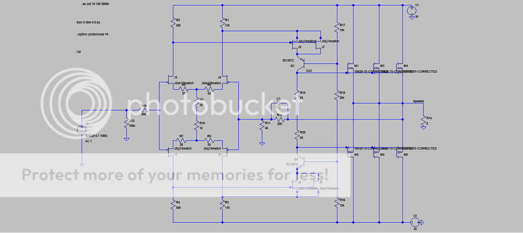
As an alternative to the Mk I circuit. this one is for the people who want more power but don't want an amp that generates heat like a bloody furnace. Or for people who want a very good Class AB amp. Output mosfets are Exicon lateral mosfets or whatever lateral mosfets you can get your hands on.
This amp performs extremely well with low bias current even into low impedance loads. I generally recommend 400mA but you can certainly go lower or higher.
The dual jfets on the folded cascode can certainly be replaced with 2sk2013/2sj313 if that is what you want to do.
I haven't added every detail on circuit (I am lazy)
I built this one a long time ago, it's a very good amp. I'll build up another version soon.
All inspiration and credit comes from reading firstwatt articles.
Thanks Papa
Here is the circuit.
Last edited:
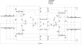
first step
correct those silly RC values in NFB loops
set OLG to have 10-ish db SUSY feedback
later we can unbalance it to invoke 2nd
I didn't sim anything , so rough/no values and still having your models ( which I obviously don't have)
correct those silly RC values in NFB loops
set OLG to have 10-ish db SUSY feedback
later we can unbalance it to invoke 2nd
I didn't sim anything , so rough/no values and still having your models ( which I obviously don't have)
Attachments
Last edited:
Yeah RC values weren't changed. I literally make hundreds of changes all the time when I'm playing with circuits, so never believe exact values in my circuits, unless I say "here is the final completed circuit"
So is the magic in R11 and R13?
Is 40 Ohms at input to ground too small?
I haven't simmed it yet
So is the magic in R11 and R13?
Is 40 Ohms at input to ground too small?
I haven't simmed it yet
Last edited:
edited previous post to include jpg
size input resistors to have sane input impedance
size resistors to gnd to have same value (as input ones) or few times up
size NFB resistors accordingly to previous ones
size lag caps according to previous ones
size JFet sssssssource resistors to have nice Iq through them
size horizontal resistor in bridge to have adequate OLG (10-15db more than CLG)
include McMillan resistor if you want , to increase DC stability , but be careful , because theu're increasing level of symmetry , which we want later to decrease intentionally
Should feedback resistance be increased. It seems input impedance will be extremely low the way it is.
Dodo
re-read #6 and take it in exact order , except with horizontal resistor in bridge - size it in step No.3 , right after resistors to gnd
ok : to have it numbered :
1. size input resistors to have sane input impedance
2.size resistors to gnd to have same value (as input ones) or few times up
3.size horizontal resistor in bridge to have adequate OLG (10-15db more than intended CLG)
4.size NFB resistors accordingly to previous ones
5.size lag caps according to previous ones
off course - prior to everything - size JFet sssssssource resistors to have nice Iq through them
include McMillan resistor if you want , to increase DC stability , but be careful , because theu're increasing level of symmetry , which we want later to decrease intentionally ; few tricks to do that , still having direction we want ....
Last edited:

Hahaha.
Ok I'm really sleeping now.
Thank you ZM for the circuit, definitely some exercise for my dumb brain.
Ok I'm really sleeping now.
Thank you ZM for the circuit, definitely some exercise for my dumb brain.
Had to change bc557/547 to to220 device, too much current through folded cascode in super symmetrical circuit.
The interest is waning in this super symmetrical circuit by the picosecond. Looks absolutely straight forward but I am not having any success.
The only reason to pursue it is for the increased power and the constant current through the power supply could be considered a benefit (as well as smaller powersupply caps). Definitely the best way to make powerful amps (eg over 50W).
Not sure if it is worth it for anything under 50W.
I've got a bloody headache. Hahahaha
Last edited:
Changing rails to +/-23V on super symmetric circuit since that is what everyone has laying around, and 100W is plenty for most people.
I would argue that even for amps under 50W, it's a preferable scenario. You get voltage swing on the cheap, so rails can be lowered and biased raised. I have found balanced/bridged amps to be a bit more dynamic than their SE counterparts. Don't seem to get as stressed out as their hi rail voltage, SE brethren when pushed. That being said, if you have 90+dB speakers, there may be arguments about excess. I do believe these type designs like to be pushed. Then again, this could simply be a function of how it is tweaked and setup.
it's hard to go below 80Vpp (100Wrms/8R)
that's the sole reason why I don't have any of those - simply not needing that sort of power
and I avoid AB class all the time , at least for amps I'm making for my self
that's the sole reason why I don't have any of those - simply not needing that sort of power
and I avoid AB class all the time , at least for amps I'm making for my self
I would argue that even for amps under 50W, it's a preferable scenario. You get voltage swing on the cheap, so rails can be lowered and biased raised. I have found balanced/bridged amps to be a bit more dynamic than their SE counterparts. Don't seem to get as stressed out as their hi rail voltage, SE brethren when pushed. That being said, if you have 90+dB speakers, there may be arguments about excess. I do believe these type designs like to be pushed. Then again, this could simply be a function of how it is tweaked and setup.
I prefer simple low parts count amps so any amp under 50 Watts will be simpler (less parts) than a bridged amp.
Balanced amps certainly have their place. I'm more of an SIT2/Aleph/Mu Follower and tweaked symmetric amps eg F6 etc. I lost interest in the whole super symmetry thing after building highly efficient speakers.
I'm still interested to see what Ultra symmetry is about, maybe it's not what I assumed it was.
- Status
- Not open for further replies.
- Home
- Amplifiers
- Pass Labs
- The eSCAPEd Goat MkII