Hi everybody!
I mean the following problem:
http://www.audiograph.se/subpages/technical/whatmakesagoodamplifier.htm
Can anybody explain this please? 🙂
Is it common that an amp "sees" an impedance 4 times less than the nominal impedance of the loudspeaker? Or can it be 2 times less or 2 times more and so on?
What are the deciding factors?
Is it a part of a larger and overlooked "amplifier-loudspeaker inteface" problem?
best,
graaf
Attachments
Hi,
my reading has revealed that it is possible for the speaker to demand much larger peak currents than a simple Vpk/Re or Vk/Rload would predict.
I have accepted the argument that states that peak transient current approaches three times the current that using nominal impedance would predict and design the output stages to meet that demand.
But, I have no proof of how accurate these guessimates/findings are.
Hi,
Douglas Self addressed this problem in this article :
"Loudpseakers undercurrents"
Electronics World, February 1998, p98-99.
More current demand than the voice coil DC resistance would demand can happen with asymetrical signals. Self thinks that a previous paper by Ottala in 1983 overestimated the problem.
Hi,
I notice they use a speaker with a spectacularly bad impedance curve.
The square wave impedance curve is a joke and is simply not impedance.
Once you start fudging about you can show almost anything you like.
I would not argue with AT's guesstimate for the current limiting
of a nominal imnpedance load for a load tolerant amplifier.
🙂/sreten.
forr said:Hi,
Douglas Self addressed this problem in this article :
"Loudpseakers undercurrents"
Electronics World, February 1998, p98-99.
More current demand than the voice coil DC resistance would demand can happen with asymetrical signals. Self thinks that a previous paper by Ottala in 1983 overestimated the problem.
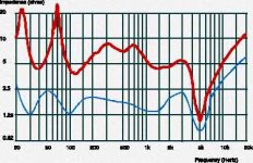
and what about the measurement the graph of which I have attached above?
this is an actual measurement of an actual loudspeaker
the upper red corresponds to a conventional measurement the loudspeaker impedance with sine wave signal
the lower blue graph corresponds to a measurement using a square wave signal
The reason for this is that square waves consist of a large amount of sine waves, as does music. The square wave is of course not an equivalent of music, but for this test it was an easy way of showing that a complex signal (not just a simple sine wave signal) may make the load, from the amplifier point of view, very low.
best,
graaf
sreten said:Hi,
I notice they use a speaker with a spectacularly bad impedance curve.
true, perhaps to illustrate the problem better?
sreten said:
The square wave impedance curve is a joke and is simply not impedance.
a joke? what do You mean?
what is impedance? is there "using of a sine wave signal" in the definition of impedance?
I am just asking 🙂
best,
graaf
You can plot the impedance of your own speaker easily with a meter that covers the required frequency range. Doug Self's method works well, connect a 600 ohm resistor in series with the speaker and drive this from 6 volts RMS. You can read in millivolts across the speaker the equivalent impedance at an frequency. So 4 millivolts is 4 ohms etc. Think I have remembered the values correctly.
And yes it is crazy- My B&W 703 an 8 ohm speaker has a 3 ohm minima !
And yes it is crazy- My B&W 703 an 8 ohm speaker has a 3 ohm minima !
Mooly said:You can plot the impedance of your own speaker easily with a meter that covers the required frequency range. Doug Self's method works well, connect a 600 ohm resistor in series with the speaker and drive this from 6 volts RMS. You can read in millivolts across the speaker the equivalent impedance at an frequency. So 4 millivolts is 4 ohms etc. Think I have remembered the values correctly.
And yes it is crazy- My B&W 703 an 8 ohm speaker has a 3 ohm minima !
would this measurement be equivalent to a measurement that uses square wave signal?
best,
graaf
Good question, and I don't really know the answer to that one. I suspect not, certainly in the way you mean. Hard to explain this, the effect of the 600 ohms means the speaker is undamped, it's not like feeding it from a low impedance source. Dunno is the answer, try it 🙂
I will add to that, squarewave testing while incredibly useful in amplifier measurements etc, bears no relation whatsoever to anything you will see off a disc. The C.D. format cannot even reproduce a 1Khz squarewave that would be considered even "acceptable" in anything else. The 44.1 Khz sample rate ensures that. Music certainly contains nothing like this anyway.
Mooly said:Good question, and I don't really know the answer to that one. I suspect not, certainly in the way you mean. Hard to explain this, the effect of the 600 ohms means the speaker is undamped, it's not like feeding it from a low impedance source. Dunno is the answer, try it 🙂
well, the problem is that to be able to compare I would have to try the measurement with square wave signal too, that is something that I am not able to do

but I do also believe that it is not really necessary because we have so many experienced and knowledgable people here at diyaudio that can answer my questions without any difficulty 🙂
they did all this many times
the only problem is to draw their attention to this little thread 🙂
best,
graaf
I don't pretend to have gotten into the details of this, but it would seem desirable to know both the impedance and the phase angle. One of the examples in the manual for the ancient GR 1603 Z-Y bridge was the measurement of a loudspeaker, with the results plotted as a circle on the complex impedance plane. It's quite revealing of the complexity (no pun intended) of the response. Another way of appreciating the problem is to look at electrical/spice models for a speaker. Your speaker if possible, but then you'll have to measure and create the model. The speaker stores energy, so you'll find some reactance values all out of proportion to what you might expect. IMO, things aren't usually as bad as the worst case scenario, but throw in a crossover design that was optimized for sound and no consideration to impedance, and I can see where an amp might protesteth loudly.
This is a good question, but I don't think it bears any relation to what actually happens in a real world audio set-up.
A squarewave is some fundamental frequency and the odd harmonics extending out to infinity. The laboratory sig/gen is a signal that tries to come as close to an infinite rate of change of voltage (up to some pre determined level) in zero time. To quote Conrad, "The speaker stores energy". You cannot just "turn off" the current in an inductive circuit like a speaker. The current in the voice coil will decay, not stop, due to the collapsing magnetic field. The speaker would have to be tested from an amp with something approaching zero ohms output impedance. I would imagine the results would be different for every amp it was tested on.
Testing with sine waves does give a repeatable meaningful answer.
Regards Karl
graaf said:
what is impedance? is there "using of a sine wave signal" in the definition of impedance?
I am just asking 🙂
best,
graaf
Hi,
Impedance varies with frequency, its easiest to
measure with a sine wave of variable frequency.
A square wave has 1 x fundamental + 1/3 3rd harmonic + 1/5 5th
harmonic + 1/7 7th harmonic etc .... . Contrary to the statement
in a post further above, a CD player produces a 1KHz square wave
accurate to the 1/19 19th harmonic, this is hardly not a square wave.
I simply do not believe the "square wave" impedance graph.
Square wave rms voltage / rms current would not look like that.
You could say simply use pink noise and rms voltage / rms current,
which would give you a complex number for impedance, but how
useful would that number be ?
Square wave impedance is a useless obfuscating concept AFAICT.
🙂/sreten.
sreten said:
I simply do not believe the "square wave" impedance graph.
Square wave rms voltage / rms current would not look like that.
are You sure? the guys from Audiograph seem to be quite credible:
AudioGraph manufactures computerized audio measuring systems and measure audio products on requests. Among our customers you will find Sony, Alpine, Volvo, Nokia, Clarion, harman/kardon, Teac, Rockford Fosgate, Zeck...
see: http://www.audiograph.se/index.htm
credentials from Rockford Fosgate: http://www.rockfordfosgate.com/products/powercube_about.asp
sreten said:
You could say simply use pink noise and rms voltage / rms current,
which would give you a complex number for impedance, but how
useful would that number be ?
I don't know
and how useful is nominal impedance number based on sine wave measurement?
which of them would be more misleading WRT to voltage and current requirements of a particular loudspeaker?
best,
graaf
graaf said:
are You sure? the guys from Audiograph seem to be quite credible:
see: http://www.audiograph.se/index.htm
credentials from Rockford Fosgate: http://www.rockfordfosgate.com/products/powercube_about.asp
I don't know
and how useful is nominal impedance number based on sine wave measurement?
which of them would be more misleading WRT to voltage and current requirements of a particular loudspeaker?
best,
graaf
Hi,
I'm having a gullibility problem here. The (one man) product is
hardly rocket science and in the overall scheme of things its a
one trick pony rather than a comphrehensive test system for
amplifier testing in all its myriad forms.
Somebody move this to car audio (amplifiers) where it belongs .....
🙂/sreten.
Hi,
In post 7, I have quoted Doug Self's method but got the decimal in the wrong place. It is 6 Volts RMS 600 Ohm and the reading is such that 40 Millivolts not 4 would be the reading for a 4 ohm impedance. Sorry for that error.
The 1Khz squarewave reproduced off disc, if you view this from a test C.D. (Philips SBC429 for example) you will see that the reproduced signal is anything but square. The rise times are severely limited (as they must be with the 22.05Khz absolute upper limit imposed by the 44.1 Khz sampling frequency) and the following anti alias filtering, such that if you feed say a 6 Khz square wave signal through the same signal path it will more closely resembles a triangular wave. If this were an amplifier it would be deemed unacceptable as it would be unable to reproduce anything approaching a square wave at higher frequencies.
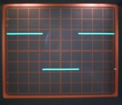
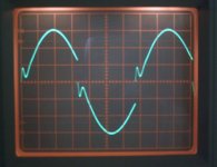
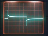
Back to the speakers, and although this does not prove anything it may be of interest to some. The 600 ohm 6 Volt test. I have a couple of screen shots here taken from the speaker terminals of a Celestion SL100, A small 2 Way bookshelf speaker. The input was a square wave.
In post 7, I have quoted Doug Self's method but got the decimal in the wrong place. It is 6 Volts RMS 600 Ohm and the reading is such that 40 Millivolts not 4 would be the reading for a 4 ohm impedance. Sorry for that error.
The 1Khz squarewave reproduced off disc, if you view this from a test C.D. (Philips SBC429 for example) you will see that the reproduced signal is anything but square. The rise times are severely limited (as they must be with the 22.05Khz absolute upper limit imposed by the 44.1 Khz sampling frequency) and the following anti alias filtering, such that if you feed say a 6 Khz square wave signal through the same signal path it will more closely resembles a triangular wave. If this were an amplifier it would be deemed unacceptable as it would be unable to reproduce anything approaching a square wave at higher frequencies.
Back to the speakers, and although this does not prove anything it may be of interest to some. The 600 ohm 6 Volt test. I have a couple of screen shots here taken from the speaker terminals of a Celestion SL100, A small 2 Way bookshelf speaker. The input was a square wave.
Attachments

- Status
- Not open for further replies.
- Home
- Loudspeakers
- Multi-Way
- "The Dynamical Loudspeaker Impedance"?