For nearly two years I've been trying to figure out how to make a loudspeaker that has wide horizontal directivity and narrow vertical directivity:
https://www.diyaudio.com/community/threads/the-nightmare-before-labor-day.374570/
The subjective data seems to indicate that this beamwidth is ideal: https://www.audiosciencereview.com/...ootout-between-jbl-m2-and-revel-salon-2.1844/

Something like the Danley SH-64 seems like an obvious choice, but they are HUGE. Thirteen cubic feet and 197lbs; much bigger than your average subwoofer. I appreciate the technology, but I don't need to hit 140dB in my living room.
The response and the beamwidth of arrays is CLEARLY IMPROVED by curving them, and the D.B. Keele CBT papers illustrate this really well.
So that got me messing around with various variations of curvature, crossover, and driver spacing.
After messing around for a while, I found that some of the best results can be achieved by using an array that's PHYSICALLY converging but ACOUSTICALLY expanding.
Let me elaborate on that statement. In a nutshell, a multi-way loudspeaker on a flat baffle will tend to have a wavefront that's curved. This is because the crossovers introduce a delay.

For instance, here's a picture of the Snell Acoustics XA Reference, designed by @SpeakerDave. The crossover point is 250Hz for the woofers. The slope is something like 18dB per octave. This will tend to introduce a delay of about 3ms - or about forty inches!!! In the real world, the actual delay will depend a lot on the passive crossover configuration. Theoretically, a third order crossover introduces 270 degrees of delay (90 degrees for each order.) The net effect is that the woofer is delayed by about 3ms. (Sound travels 13.5 inches in one second, 250Hz is fifty four inches long, 75% of fifty four inches is 40.5 inches.)

After tinkering for a while in Vituixcad I began to realize that the baffle needs to CONVERGE in order to produce a flat wavefront. This probably seems counter-intuitive; the Snell baffle is flat. Why would it generate a curved wavefront? And the answer is in the passive crossover. A third order crossover at 250Hz (like in the Snell XA Reference) produces about 40.5 inches in delay! Due to the fact that the tweeter in the center of the array isn't delayed remotely as much by the crossover, the wavefront of the array is significantly curved. The wavefront isn't curved physically; it's curved by the crossover.
With that knowledge in hand, I began to tinker with WMTMW arrays, and manipulating the curvature of the loudspeaker baffle, to achieve beamwidths which wouldn't be otherwise possible.
https://www.diyaudio.com/community/threads/the-nightmare-before-labor-day.374570/
The subjective data seems to indicate that this beamwidth is ideal: https://www.audiosciencereview.com/...ootout-between-jbl-m2-and-revel-salon-2.1844/
Something like the Danley SH-64 seems like an obvious choice, but they are HUGE. Thirteen cubic feet and 197lbs; much bigger than your average subwoofer. I appreciate the technology, but I don't need to hit 140dB in my living room.
The response and the beamwidth of arrays is CLEARLY IMPROVED by curving them, and the D.B. Keele CBT papers illustrate this really well.
So that got me messing around with various variations of curvature, crossover, and driver spacing.
After messing around for a while, I found that some of the best results can be achieved by using an array that's PHYSICALLY converging but ACOUSTICALLY expanding.
Let me elaborate on that statement. In a nutshell, a multi-way loudspeaker on a flat baffle will tend to have a wavefront that's curved. This is because the crossovers introduce a delay.
For instance, here's a picture of the Snell Acoustics XA Reference, designed by @SpeakerDave. The crossover point is 250Hz for the woofers. The slope is something like 18dB per octave. This will tend to introduce a delay of about 3ms - or about forty inches!!! In the real world, the actual delay will depend a lot on the passive crossover configuration. Theoretically, a third order crossover introduces 270 degrees of delay (90 degrees for each order.) The net effect is that the woofer is delayed by about 3ms. (Sound travels 13.5 inches in one second, 250Hz is fifty four inches long, 75% of fifty four inches is 40.5 inches.)
After tinkering for a while in Vituixcad I began to realize that the baffle needs to CONVERGE in order to produce a flat wavefront. This probably seems counter-intuitive; the Snell baffle is flat. Why would it generate a curved wavefront? And the answer is in the passive crossover. A third order crossover at 250Hz (like in the Snell XA Reference) produces about 40.5 inches in delay! Due to the fact that the tweeter in the center of the array isn't delayed remotely as much by the crossover, the wavefront of the array is significantly curved. The wavefront isn't curved physically; it's curved by the crossover.
With that knowledge in hand, I began to tinker with WMTMW arrays, and manipulating the curvature of the loudspeaker baffle, to achieve beamwidths which wouldn't be otherwise possible.
Here's some graphs that illustrate what the passive crossover does to phase.

1) In a loudspeaker with no delay, the crossover introduces no delay (because there's no crossover.) The motor of the loudspeaker itself may introduce delay (due to inductance of the motor itself.)

2) In a loudspeaker with a 2nd order crossover, the crossover itself will introduce about 90 degrees of delay. At 1khz this is equivalent to 3.375"

3) In a loudspeaker with a 4th order crossover, the crossover itself will introduce about 180 degrees of delay. At 1khz this is equivalent to 6.75"
1) In a loudspeaker with no delay, the crossover introduces no delay (because there's no crossover.) The motor of the loudspeaker itself may introduce delay (due to inductance of the motor itself.)
2) In a loudspeaker with a 2nd order crossover, the crossover itself will introduce about 90 degrees of delay. At 1khz this is equivalent to 3.375"
3) In a loudspeaker with a 4th order crossover, the crossover itself will introduce about 180 degrees of delay. At 1khz this is equivalent to 6.75"
Wide horizontal, narrowish vertical is exactly what I've been tinkering with. In a small form-factor, the Perlisten tested by Erin is a great example. Look at the floor and ceiling response. I'm using more conventional drivers and waveguide tweeter, but the mains will be WMTMW for exactly the reason you point out. I started down this road in 2015 with the following design (not yet finished):


Hey Patrick
This seems to go in the opposite direction of what you have been driving towards for many years, making a lot of unity horns and waveguides?!
I've been following you all the way and been highly, highly, impressed with you progress, insights, results and the sheer number of projects.
I wonder how you have not come to the conclusion to go in a new direction?
Have the listening results of you different designs not been good enough?
I have only recently started working with waveguides, and there seems to be a lot of benefits, but I also feel there might be some drawbacks.
But I find it a little difficult to pinpoint what is real and what is imagined, meaning, that to fin out one should change only one parameter at a time, e.g. making a 2 way with either waveguide or not waveguide of the same dome tweeter, ensuring exact on axis response via DSP.
The shoot out btw. M2 and Saloon2, I think is a bit difficult to conclude if horn/waveguide is better or worse than a plain dome, as the 2 speakers are so different in the makeup, drivers, topology, size etc.
Not that I doubt the listening result. I have heard many horns on shows and I didn't really like any of them .... maybe because I have told my mind "I don't like horns" ... who knows!
By the way, the saloon actually uses a small waveguide for the tweeter.
Maybe it's about not going too far. Maybe best result is still CD but not too high directivity.
KR Baldin
Didn't the fractal array get that right?

https://www.diyaudio.com/community/...raight-cbt-with-passive-xos-and-no-eq.330031/
https://www.diyaudio.com/community/...raight-cbt-with-passive-xos-and-no-eq.330031/
Hi Patrick,
If you consider verticaly aligned arrangement: have you read Horbach-Keele approach?
It opens possibility to have controled vertical directivity control over a wide bandwith of spectrum( 200hz to whatever* for 2m height loudspeakers). It's not dissimilar to Dave Smith's aproach on Snell's, except it is not locked into a wide vertical pattern ( which is the case with the XP).
The range goes from 113* to 67* with some artefacts creeping in the narrower it goes ( but still manageable). *It'll ask for a waveguided dome tweeter or compression driver if you target directivity control in the upper octave though ( like the Snell's).
I get you approach things with IIR filters in mind and this ask for FIR implementation, but it is an option to consider in my view ( it fullfil your initial requirements).
http://www.xlrtechs.com/dbkeele.com/PDF/Keele (2007-09 AES Preprint)- Linear Phase Digital Crossover Flters Part 1.pdf
http://www.xlrtechs.com/dbkeele.com/PDF/Keele (2007-09 AES Preprint)- Linear Phase Digital Crossover Flters Part 2.pdf
I agree with Norman Bates, Dunlavy approach with the Magnus involved flat front baffle, delay to compensate emmission points and a definition of FIR filters in the interview in which he talk about them i've read.
Bring in the Horbach Keele approach and i think it could bring benefits ( if you can live with very big towers!), one of them being constant and smooth vertical coverage (as pointed by Baldin) which could be taylored on the horizontal with the waveguide if needed/wanted).
Wesayso, aren't fractal array based on this filters( H-K) too?
Last edited:
Hi Patrick,
If you consider verticaly aligned arrangement: have you read Horbach-Keele approach?
It opens possibility to have controled vertical directivity control over a wide bandwith of spectrum( 200hz to whatever* for 2m height loudspeakers). It's not dissimilar to Dave Smith's aproach on Snell's, except it is not locked into a wide vertical pattern ( which is the case with the XP).
The range goes from 113* to 67* with some artefacts creeping in the narrower it goes ( but still manageable). *It'll ask for a waveguided dome tweeter or compression driver if you target directivity control in the upper octave though ( like the Snell's).
I get you approach things with IIR filters in mind and this ask for FIR implementation, but it is an option to consider in my view ( it fullfil your initial requirements).
http://www.xlrtechs.com/dbkeele.com/PDF/Keele (2007-09 AES Preprint)- Linear Phase Digital Crossover Flters Part 1.pdf
http://www.xlrtechs.com/dbkeele.com/PDF/Keele (2007-09 AES Preprint)- Linear Phase Digital Crossover Flters Part 2.pdf
I agree with Norman Bates, Dunlavy approach with the Magnus involved flat front baffle, delay to compensate emmission points and a definition of FIR filters in the interview in which he talk about them i've read.
Bring in the Horbach Keele approach and i think it could bring benefits ( if you can live with very big towers!), one of them being constant and smooth vertical coverage (as pointed by Baldin) which could be taylored on the horizontal with the waveguide if needed/wanted).
Wesayso, aren't fractal array based on this filters( H-K) too?
Literally one of my favorite audio papers of all time. Everyone needs to go read it. And the fractal array referenced by WeSaySo is basically the same array, but made two dimensional instead of one dimensional.
I'll post the sims today, but the fundamental difference that I came up with, is making the array CONCAVE instead of CONVEX.
In the Horbach Keele paper, the range of vertical beamwidths is about 90 - 180 degrees. They used an angle of about 70 degrees, which was a compromise between driver spacing and beamwidth.
It occurred to me - what if you used the SPACING of the Horbach Keele design, and then curved the array to be CONCAVE?
Again, I'm still tinkering with the design, but it seems to offer what I'm looking for: wide horizontal beamwidth, narrow vertical beamwidth, using passive xovers.
If I was willing to run six amplifiers and six channels of DSP I could get any wavefront I feel like really. I would like to avoid that if possible because this will end up in a living room and there's already too much gear in there already.
Another "nice" thing that I've found about this design, is that it delivers preposterous amounts of bass. So it might be possible to even get subwoofer levels of bass out of the mains. Basically a fraction of the drivers are active in the midrange, and as frequencies get lower and lower, additional drivers become used. (Similar to the Snell "eXpanding Array" concept, where the array becomes acoustically larger at low frequencies.)
The design WILL require two channels of DSP, because the low frequencies are so loud, but that's not an issue. I just don't want to run SIX channels of DSP.
I agree the complexity can discourage implementation of a multi amped six way.
I'm curious to see what you came up with. What is your target for vertical coverage angle?
About convex arrangement this is how i see Dunlavy implemented the drivers in eg Sc-VI.
https://images.app.goo.gl/NVr1Bmc4k1TXypFU7
In my understanding it isn't for the same reason than your concern but maybe there is other effects at play?
My comment about dsp/delay is related too as it gives opportunity to move drivers 'virtual' location along Z axis despite having a flat front, but of course is moot if you go passive.
From your description you follow 'expanding array' philosophy 'textbook'. I remember a thread here where member Ra7 implemented it and Dave Smith ( SpeakerDave) gave a variation along the theme ( using differents drivers with more typical filtering than the kind of 'shade' he implemented in the commercial Snell units he designed which used the same 8" iirc).
I'm sure you know it but for those interested this is a good read too:
https://www.tnt-audio.com/intervis/david_smith_e.html
Unexpectedly, the concave array has WIDER beamwidth lol
Go figure

Here's the beamwidth of the array when the baffle is flat. The vertical beamwidth gradually widens, from thirty degrees to sixty degrees, as frequencies get lower.

Here's the beamwidth of the array when the baffle is concave. The vertical beamwidth gradually widens, from fifty to seventy five degrees. I'm not excited that the beamwidth is actually WIDER, but I do appreciate that it's more consistent. Arrays control directivity via destructive interference and you can see that the efficiency of the concave array is about 3dB lower at 1khz. I'm not really worried because power handling is ridiculous, with six drivers. Power handling should be about 300 watts.

Here's the filter.

Here's the filter response.
This filter is basically a variation on the passive filter that JBL uses in it's flat-faced CBT arrays. The way that the filter works, is that instead of using resistors (like in the Parts Express CBTs) it uses cascaded second order filters. So the crossover point of the array doesn't vary a great deal but the phase of the filters does.

Here's some more detail on how the combination of delay introduced by the filter and driver offset interact. Basically the crossover filter delays the radiation of the sound; to compensate for that delay THE MIDBASSES MUST BE PUSHED BACKWARDS. And the net effect produces the wavefront that we want. Note that this isn't 100% finished at all; I still need to mess around with the filter delays and how far back the drivers are pushed.
Go figure
Here's the beamwidth of the array when the baffle is flat. The vertical beamwidth gradually widens, from thirty degrees to sixty degrees, as frequencies get lower.
Here's the beamwidth of the array when the baffle is concave. The vertical beamwidth gradually widens, from fifty to seventy five degrees. I'm not excited that the beamwidth is actually WIDER, but I do appreciate that it's more consistent. Arrays control directivity via destructive interference and you can see that the efficiency of the concave array is about 3dB lower at 1khz. I'm not really worried because power handling is ridiculous, with six drivers. Power handling should be about 300 watts.
Here's the filter.
Here's the filter response.
This filter is basically a variation on the passive filter that JBL uses in it's flat-faced CBT arrays. The way that the filter works, is that instead of using resistors (like in the Parts Express CBTs) it uses cascaded second order filters. So the crossover point of the array doesn't vary a great deal but the phase of the filters does.
Here's some more detail on how the combination of delay introduced by the filter and driver offset interact. Basically the crossover filter delays the radiation of the sound; to compensate for that delay THE MIDBASSES MUST BE PUSHED BACKWARDS. And the net effect produces the wavefront that we want. Note that this isn't 100% finished at all; I still need to mess around with the filter delays and how far back the drivers are pushed.

Here's the layout of the drivers (currently). It still needs some tweaking to produce the desired wavefronts.

Impedance is pretty well behaved.
Pardon me asking, trying to understand, what does wavefront and long throw mean in this case. Does it just mean narrow vertical polar response?
Wavefront seems to mean waves arriving together at same phase, so figuring it would mean here that full bandwidth is arriving at same phase and you are looking to achieve this with passive filters only? How does this relate to curved or flat wavefront as the ear is only at one point and it wouldn't matter which one it is for everything to arrive at same phase regardless? With array this happens on very narrow vertical window, there is path length difference and destructive interference off-axis, phase is not same across the board, or is it? Trying to get imagination going with this 🙂
Wavefront seems to mean waves arriving together at same phase, so figuring it would mean here that full bandwidth is arriving at same phase and you are looking to achieve this with passive filters only? How does this relate to curved or flat wavefront as the ear is only at one point and it wouldn't matter which one it is for everything to arrive at same phase regardless? With array this happens on very narrow vertical window, there is path length difference and destructive interference off-axis, phase is not same across the board, or is it? Trying to get imagination going with this 🙂
"Long Throw" basically means narrow vertical directivity.
@FoLLgoTT achieved this using DSP and a bunch of amps:
https://www.diyaudio.com/community/...directivity-and-horbach-keele-filters.284117/
I'm trying to determine if it's possible to do it passively.
A straight line array can do it, but the treble on a straight line array isn't great. So I'm basically trying to figure out if the delays introduced by a passive crossover can be offset by recessing the drivers.
https://www.avsforum.com/threads/radical-speaker-design.3053246/I'm trying to determine if it's possible to do it passively.
This is bbutterfield's speaker that he made based on the simplified fractal idea, fully passive. So yes it is possible. Matching the vertical directivity of a tall array is very hard to do without using a tall tweeter.
Another bit of description here
https://www.diyaudio.com/community/...rs-some-startup-questions.352329/post-6163781
This whole idea seems counter productive to me unless you want to restrict the listening position to a very small area.A straight line array can do it, but the treble on a straight line array isn't great. So I'm basically trying to figure out if the delays introduced by a passive crossover can be offset by recessing the drivers.
Listening position is restricted vertically - it is the height of the ear above the floor, while we are sitting - so restricted vertical dispersion of the loudspeaker (i.e. narrow vertical directivity) will not restrict listening area. Listening area can be very wide (horizontally), if the horizontal dispersion of the loudspeaker is wide.This whole idea seems counter productive to me unless you want to restrict the listening position to a very small area.
That isn't what I meant, converging the array makes it distance dependent.Listening position is restricted vertically - it is the height of the ear above the floor, while we are sitting - so restricted vertical dispersion of the loudspeaker will not restrict listening area. Listening area can be very wide (horizontally), if the horizontal dispersion of the loudspeaker is wide.
Trying thinking this, and while I know about nothing on passive crossovers it seems like the MEH concept is what you are chasing here 😀 A MEH works with passive crossover and does similar thing while downside is being bulkier in comparison to array having similar (vertical) directivity control. Perhaps there is also problem to get the vertical much narrower than horizontal with MEH, try and do something to it within a horn and now there is pattern flip to deal with.I'm trying to determine if it's possible to do it passively.
While arrays have problems with high treble I suspect you need to pursue this from the MEH perspective, make the treble / highs good with MEH concept and before it gets too bulky in size expand to vertical array of woofers. You could perhaps make the low section with active crossover and MEH part with passives to keep complexity manageable?
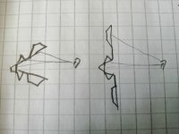
Perhaps array two or more very narrow pattern MEH side by side to achieve wide horizontal and narrow vertical pattern and simple crossover, then one pair of woofers above and below? Take big MEH then grab from top and bottom lip (and sides) and peel it open like banana with drivers and all, until the depth is fine, exchanged to height (and width). Just cut of the sides as you wanted horizontal wide and no you are left with top and bottom straight up, some kind of horn on the middle. You could just calculate same path length difference from listening position to woofers (that are now in the peeled up vertical parts) as if they were inside the horn, just slide them up / down to achieve this, and keep the crossover same?
edit. attached quick sketch of peeled MEH, it should work with same xover in both cases I think, apart from perhaps some pad adjustment, as long as path length difference from woofer to ear stays the same. There would be difference in pattern with both of thes, but vertical should be narrow, horizontal could be wide, passive xo, not too bulky perhaps. Perhaps it doesn't workout without DSP, bass would benefit from DSP so perhaps the woofers are actively controlled and the meh part passively.
All in all its just a set of compromises to take. Will follow what you come up with 🙂
ps. Trying to search with some buzzwords and your previous threads come up on top 😀
Attachments
Dunlavy's are known to have a small listening spot. I haven't listened to SC VI but i have a SCVI and it was the case with them.
In fact this is design goal from Dunlavy's interview. Not this is unlistenable outside it, but the default seems to vanish when you are at correct location and there is a 'contrast' thing happening.
From the stereophile Snell review of XA it seems they are much more friendly if you want a large sweetspot.
I think the key here is in the uniform and smooth (vertical) dispersion ( can be seen in 'measurements' fig 6 of the article).
I wonder if the waveguide isn't part of this too.
https://www.diyaudio.com/community/...-array-28-tc9fd18.349356/page-13#post-6590599
Job done... limited vertical directivity and wide horizontal directivity.


A WWmmmmTmmmmWW, but created with active DSP
Loosely based on the work we did in nc535's thread...
Job done... limited vertical directivity and wide horizontal directivity.
A WWmmmmTmmmmWW, but created with active DSP
Loosely based on the work we did in nc535's thread...
- Home
- Loudspeakers
- Multi-Way
- The Diyaudio Long Throw Array