...and after playing with P3 on the F5T and BA-3, I can say that personally, tuning for minimum THD does not sound the best to me.
maybe move the inner transistor 40mm closer to the transformer, for more effective use of the sinks?
For clarification, for inner transistor you mean Q1 ? And by mean transformator you mean Jensen or toroid ?
Didiet
You are welcome to put more current through them, but any noise is not going to make it
through the 10K + 1,000 uF RC filter, and if it did it would be taken down another 20 dB
or so by feedback.
😎
Yes, I was mostly concerned about the soft voltage regulation with such low current. The gate bias voltage would drift around somewhat with power supply variations. Maybe 3 series red LEDs could be used in place of the zeners?
yes. Q1. and Jensen transformer.For clarification, for inner transistor you mean Q1 ? And by mean transformator you mean Jensen or toroid ?
Didiet
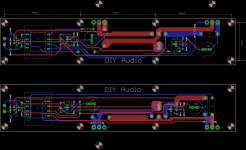
I would move the trace for the Q2 gate resistor (R12) to the top of the board, so you don't need to bite a piece of the source trace. You can easily do it in the center of the board, nothing on the bottom layer there.
Ok, I see the difficulties, but give it a though! 🙂
1) Move Gate traces on the top?
2) Make a turn around 7 and 8 pin of the input transformer to put that gate trace above. Does it make any sense? (Still at work... brain is melting) 🙂))
Ok, I see the difficulties, but give it a though! 🙂
1) Move Gate traces on the top?
2) Make a turn around 7 and 8 pin of the input transformer to put that gate trace above. Does it make any sense? (Still at work... brain is melting) 🙂))
Last edited:
...and after playing with P3 on the F5T and BA-3, I can say that personally, tuning for minimum THD does not sound the best to me.
Just curious. Did it sound best (to you) when you adjusted P3 to emphasize the second over the 3rd harmonic? Did you find any advantage of adjusting P3 over initial settings, with equal resistance on each side as best you could measure?
Steve
Member Didiet78 has done some preliminary layout, (Thanks a million! It looks wonderful!!)
The floor is open for discussion. 😀
How about a pair of test points for each source resistor, for easier biasing?
How about a pair of test points for each source resistor, for easier biasing?
Stand the resistor off the pcb a 1/4" and you will have good ventilation and a great place to clip your meter onto. 🙂
Just curious. Did it sound best (to you) when you adjusted P3 to emphasize the second over the 3rd harmonic? Did you find any advantage of adjusting P3 over initial settings, with equal resistance on each side as best you could measure?
Best sounding to me was actually quite close to even resistance... Which was a dominant 2nd harmonic at the 1w level.
If you have the ability to look at the distortion residual waveform, such as with a distortion analyzer, adjust P3 for the ultimately smoothest wave.
In my experience adjusting for absolute minimum THD makes for a very fast, detailed, intricate, and precise sound. It also has no soul... These amps can be adjusted to be very pretty at no significant penalty in resolution. Make the 2nd dominant at 1w and it should all fall into
place .
I would move the trace for the Q2 gate resistor (R12) to the top of the board, so you don't need to bite a piece of the source trace. You can easily do it in the center of the board, nothing on the bottom layer there.
Ok, I see the difficulties, but give it a though! 🙂
1) Move Gate traces on the top?
2) Make a turn around 7 and 8 pin of the input transformer to put that gate trace above. Does it make any sense? (Still at work... brain is melting) 🙂))
Did i got it right ?
Attachments
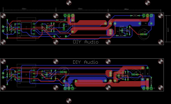
Yep! Top one is good. The bottom one is a bit too crowded around Q1. I think we can try to work it out. Will look carefully tomorrow, too late tonight.
Didiet, thanks for your afford!
Didiet, thanks for your afford!
Did i got it right ?
Looking nice already, ...but since we are asking: what about placing trimmers in paralel to R1 and R2 for variable second harmonic adjustment ?
That would be even nicer 😀
what about placing trimmers in parallel to R1 and R2 for variable second harmonic adjustment ?
If you want that type of adjustment, use the Tea-Bag PCB - they have pots in the output source resistors.
If you want that type of adjustment, use the Tea-Bag PCB - they have pots in the output source resistors.
I do have those PCBs and they are about to sing...but this is for these mosfet ones 😉...just a thought.
Change to use both transformer styles?
Would it possible to set the board up so it could use either the leaded or the pcb transformer versions similar to what was done by Permaneder on the VFET amp board?
http://www.diyaudio.com/forums/grou...ass-csx1-sony-vfet-amplifier.html#post3904854
This way those of us who participated it in the recent group buy of the leaded units don't have to re-buy or modify to make them work.
Nice job so far!
Steve
The PCB will be designed to only mount the specified Jensen transformer, but I'll look into the possibility of a second set of pads, if possible, to mount a Lundhal or something... No promises.
Would it possible to set the board up so it could use either the leaded or the pcb transformer versions similar to what was done by Permaneder on the VFET amp board?
http://www.diyaudio.com/forums/grou...ass-csx1-sony-vfet-amplifier.html#post3904854
This way those of us who participated it in the recent group buy of the leaded units don't have to re-buy or modify to make them work.
Nice job so far!
Steve
Last edited:
- Home
- Amplifiers
- Pass Labs
- The diyAudio Firstwatt F6