You can reduce H2 by using 5R degenration on the 2SJ74 (Idss matched to K170 after degen), and vgs or hfe match for current mirror.
Especially when using MOSFETs for current mirrors.
Patrick
Especially when using MOSFETs for current mirrors.
Patrick
Balanced DAO build in progress
After being under the radar for a couple of years the corona crisis finally gave me the time to finish my balanced DAO build. I'm still working on the case, but I hope to also round this up within the next month or so.
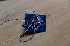
Picture shows the layout of the right channel amp core with the buffered X-feed circuit, Khozmo attenuator, voltage gain stage (HAGS), current buffer (DAO) and head phone protection circuit.
After being under the radar for a couple of years the corona crisis finally gave me the time to finish my balanced DAO build. I'm still working on the case, but I hope to also round this up within the next month or so.
Picture shows the layout of the right channel amp core with the buffered X-feed circuit, Khozmo attenuator, voltage gain stage (HAGS), current buffer (DAO) and head phone protection circuit.
Attachments

Heat dissipation will be sufficient.
Might as well answer your other question here.
The two channels of the amp are opposing and the Xfeed PCBs some 5-6 cm away from each other face to face. You can see in the picture how the actual X feed signal is wired.
As I wanted to be able to turn the Xfeed on and off I have furthermore added signal relays on the bottom side of the PCBs.
Attachments

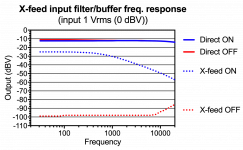
There are other ways of switching off crossfeed without affecting gain (or 10dB attenuation to be precise).
Patrick
Patrick
There are other ways of switching off crossfeed without affecting gain (or 10dB attenuation to be precise).
Don't worry. I'm doing it the way it should be done.
X-feed is turned off by opening J2 and closing J3, which is what the relay does with quite short wiring path. Attenuation does not change.
Since we are on the topic, the HAGS for the DAO SE can of course also take balanced input signal.
Two GB1 subscribers want to do exactly that.
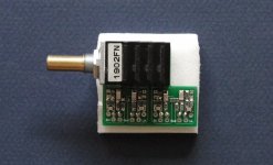
So we designed a special PCB for them, shown here with TKD 4CP-601.
For a sense of scale, the shaft is 6mm.
Patrick
.
Two GB1 subscribers want to do exactly that.
So we designed a special PCB for them, shown here with TKD 4CP-601.
For a sense of scale, the shaft is 6mm.
Patrick
.
Attachments
While we are at the buffered Xfeed input.
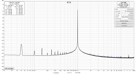
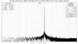
The distortion added by this module is very low (around -140dB) and somewhat difficult to measure. Attached are the measurements using Victor's oscillator, a notch filter, and software (REW) notch filter compensation. The first graph is the Xfeed measured using conventional level averaging. The second graph is the same measurements employing coherent phase averaging. The third measurement is the input signal (i.e output of oscillator) measured using coherent phase averaging.
The distortion added by this module is very low (around -140dB) and somewhat difficult to measure. Attached are the measurements using Victor's oscillator, a notch filter, and software (REW) notch filter compensation. The first graph is the Xfeed measured using conventional level averaging. The second graph is the same measurements employing coherent phase averaging. The third measurement is the input signal (i.e output of oscillator) measured using coherent phase averaging.
Attachments

Not too surprising.
Especially when the HAGS is not loading the JFET follower much, if at all.
One should bear in mind that all these numbers are achieved without global negative feedback.
Just circuit design and careful selection and matching of devices.
When you are done, you most likely would have a headphone amp better than my own.
🙂
Patrick
In trying to build dao then finding out that the parts are unobtanium, ive come across a poor man's version of it here. HotFET Pre: J-FET audio preamplifier schematics | MyElectrons
And the schematic if itll let me paste here.

Do you think this is worth building? And what would you do to make it more dao-like in terms of performance? 😀
.
And the schematic if itll let me paste here.
Do you think this is worth building? And what would you do to make it more dao-like in terms of performance? 😀
.
The link you posted points to a circuit using a single J310 as driver.
This has a transcoductance of 18mS, which is equivalent to an output impedance of 55 ohm.
Even with a 600 ohm headphone, you will not have much control.
The LU1014, in comparison, has a transcnductance of about 1S, or 1000mS.
If you want to build such a circuit, you can consider using 50x 2SK209GR in parallel to replace each of VT2 & VT4.
They will have to be matched to say 5% Idss for equal current sharing, probably each with a small source resistor, say 5R.
You will then come somewhat close to a single LU1014.
But then I thought you could still get LU1014 ?
SIT headamp or preamp
Patrick
Oh no, if you scroll down the final version is a mos ccs/jfet cascode. Looks very much like dao
I cant from korea with LU1014. The shipping price and wait time is too much. Not to mention the same has to be suffered with latfets
I cant from korea with LU1014. The shipping price and wait time is too much. Not to mention the same has to be suffered with latfets
I know what you were referring to.
I told you all I wish to tell, so I have nothing to add.
The HotFET Pre is a "J-FET audio preamplifier".
It can drive a 10k load, not 600R or 32R.
As I already said, if you cannot get LU1014, then try 50x 2SK209GR in parallel.
In stock at digikey. 200x will cost you 54 USD.
It will be super low noise as well.
Cheers,
Patrick
And 2 pairs of LU1014 from Jims Audio (ebay) cost 17USD plus 4.50USD postage.
Shipment time is ~ 2 weeks.
If that is too much for you, then you should consider building something else.
Like the Pioneer Super Linear.
Costs next to nothing, especially with the through hole version :
the Headphone amplifier
Sounds good as well. 😉
Patrick
Shipment time is ~ 2 weeks.
If that is too much for you, then you should consider building something else.
Like the Pioneer Super Linear.
Costs next to nothing, especially with the through hole version :
the Headphone amplifier
Sounds good as well. 😉
Patrick
My mistake. I misread your earlier comment. I will have to consider building the authentic dao in the near future when im freed from my other projects, thank you.
- Home
- Amplifiers
- Headphone Systems
- The DAO SE all-FET Class-A ZGF Headphone Amplifier