Hi,
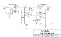
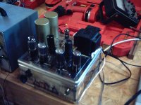
The 6N7 question by Alistair E brought my first amp to mind, so I thought I would post a picture and scheme for it. It is an adaptation of an amp shown in the 1953 issue of Practical Amplifier Diagrams. The 6N7 is used as the voltage amplifier and phase splitter. The 6V6 tubes are wired as triodes. I used a pair of found toroids for the OPT. Very high impedance primary. They have 4 equal windings on the primary, so someday I may even try it as UL. The schematic is for the original as built, I have played with it quite a bit since then, and to tell the truth I am not exactly sure where some of the parts values sit now. When I get a day or two clear I will rebuild it yet again. Great sounding amp, good for about 2.5W. I am currently using it for the rear surrounds in my multichannel setup.
Michael
Attachments
Will try it
Hi Micheal,
Thank you for your 6N7 circuit. I have some NOS 6N7 & 6N7GT on hand and will try to make one of your crackerbox amp but use 6L6 or 6AQ5A as output tubes. What is your opinion?
Cy
Hi Micheal,
Thank you for your 6N7 circuit. I have some NOS 6N7 & 6N7GT on hand and will try to make one of your crackerbox amp but use 6L6 or 6AQ5A as output tubes. What is your opinion?
Cy
Crackerbox Magic
Michael's crackerbox amp is a real beauty to listen to. I have had the rare pleasure of this experience and can recommend this amp highly.
Joe
Michael's crackerbox amp is a real beauty to listen to. I have had the rare pleasure of this experience and can recommend this amp highly.
Joe
PS and other tubes
Hi Cy,
I really like the 6V6 tube and have several vintage amps that use it as tetrode. That said, I think with a socket change a 6AQ5 would be a drop in for the circuit. The 6L6 would require a heftier power supply than I have if biased normally for the operating point and probably a bit larger of an autobias resistor, otherwise I think it should be fine. I would note that I am using a very high impedance output transformer (~15k) and that may be the secret to the sound.
Hi Joe,
Thanks for the compliment on the amp. Everyone who has listened to the amp has really liked it. I think it goes to show that one can put together a very nice sounding amp for very little money, I am sure I have less than $100 into it including the NOS tubes. I believe I will pull it off of the surround duty and put it back on the mains for a few days. I do kind of miss it.
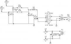
Here is the schematic of the power supply. The 10uF cap is actually two parallel 5uF ASC metallized polypropylene snubber caps, the 160uF is two parallel 80uF Sprague Atoms, and the 25uF (which is also shown in the channel schematic) is a polypropylene/oil. The voltages on the channel schematic are measured, so the 280V output is actually 294V.
Hi Cy,
I really like the 6V6 tube and have several vintage amps that use it as tetrode. That said, I think with a socket change a 6AQ5 would be a drop in for the circuit. The 6L6 would require a heftier power supply than I have if biased normally for the operating point and probably a bit larger of an autobias resistor, otherwise I think it should be fine. I would note that I am using a very high impedance output transformer (~15k) and that may be the secret to the sound.
Hi Joe,
Thanks for the compliment on the amp. Everyone who has listened to the amp has really liked it. I think it goes to show that one can put together a very nice sounding amp for very little money, I am sure I have less than $100 into it including the NOS tubes. I believe I will pull it off of the surround duty and put it back on the mains for a few days. I do kind of miss it.
Here is the schematic of the power supply. The 10uF cap is actually two parallel 5uF ASC metallized polypropylene snubber caps, the 160uF is two parallel 80uF Sprague Atoms, and the 25uF (which is also shown in the channel schematic) is a polypropylene/oil. The voltages on the channel schematic are measured, so the 280V output is actually 294V.
Attachments
- Status
- Not open for further replies.