Hello Jack,
No I have not tested with bias current. I am reading and planning a procedure to do that. For the larger version of this reduced permeability core I placed the primary in series with a 12B4A SET amplifier at 35 ma bias and did not see saturation caused distortion on the AP audio analyzer. I will keep at it.
Just considering: I have 10 of these cores, I will roll one up and send it your way if you want to do any any collaborative testing.
Thanks DT
Hello,
Rolling around on the exercise mat this morning I was thinking about testing these Home Roll transformers with applied bias current. The Bode 100 does not have any built in DC bias capabilities. The Rohde & Schwarz HM8118 LCR-Bridge here in the cage does have DC bias built in. But there is no neat sweep and plot software.
Thinking about this a little more: if the transformer secondary coil is in series with a tube amp power supply it will not be looking into a 10 Ohm injection resistor. AC wise it will be looking into the workings of the tube in parallel with the AC load. Something like a couple to a few K ohms.
So what I think I will do is connect a 2K resistor to the secondary of the injection transformer and push different bias currents through the primary and plot the inductance vs. current to see what will happen with saturation.
I am expecting to possibly see something like a sigmoid looking graph; something with a straight section in the middle with a knee at the bottom and a shoulder at the top.
Thoughts?
Thanks DT
Lots of good product information in this Vacuumschmelze publication.
https://www.vacuumschmelze.com/file...crystallineVITROPERM-EMC-Products-2016_01.pdf
https://www.vacuumschmelze.com/file...crystallineVITROPERM-EMC-Products-2016_01.pdf
Hello,
I tested this latest Home Roll transformer. There was some variation of inductance with frequency. Up to the 200ma bias limit of the HM8118 LCR Bridge I did not see any variation of inductance as the current was dialed up and then back down to zero. There were no signs of saturation with varying current.
The next test will be to install this Home Roll transformer between the power supply and an operating 12B4A Single End Triode headphone amplifier and look at PSRR and distortion of the signal injected into the Home Roll transformer.
Thanks DT
Hello,
Before I put high voltage on this transformer I thought that I would poke around a little more with this LCR meter. I got to thinking that the termination of the secondary will have a big influence the magnetic behavior of the primary and the magnetic core.
Leave the secondary coil open you have one thing, short the secondary you have something else. If you terminate the secondary coil with a 10 Ohm injection resistor the primary coil will have one inductance. If you terminate the secondary coil into the power supply of a Single End Triode amplifier you will see an entirely different primary coil inductance.
For grins I tested this Home Roll transformer under 4 different termination conditions:
At 1 volt input, 150ma bias at 1000 Hz:
Secondary coil shorted inductance measured, 2.5581uH
Secondary coil with 1R resistor inductance measured, 598.45uH
Secondary coil with 2.2K Ohms, inductance measured, 3.7033mH
Secondary coil open, inductance measured, 3.7044mH
I suspect that saturation behavior of this Home Roll transformer will strongly depend on the secondary coil termination resistance. More head scratching and testing.
Hello Jan
Thanks DT
Hello,
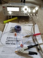
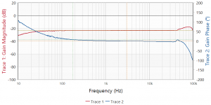
Today I installed the Home Roll injection transformer in series with The Keysight N5752A DC power supply, Transcendar model TT 106 OT Single End output Transformer and a 12B4A vacuum tube. There was a 70 Ohm Dale metal film resistor across the 600 Ohm and Com Transcendar output conductors. With a capacitor bypassed 500 Ohm cathode resistor the supply DC voltage and current was ramped up to 35 ma and back down. 35 ma times the related DC voltage is the max recommended power dissipation for the 12B4A vacuum tube.
See the attached Bode 100 plot.
Also see the plot for the Trasscendar output transformer.
I did learn at least one thing. With the injection transformer directly in series with the power supply the ability to isolate the injection transformer phase margin is lost. There is no injection resistor to sample across. To measure the input signal the input signal needs to be sampled across the injection transformer primary coil.
So far this Home Rolled injection transformer looks to function, with real world bias, at least up to 35ma. The big however is that the injection transformer PM is evident in the PSRR plot. The same fault will show up using the Jensen JT-123-BLCF as shown in the Audio Precision, Technote 106.
I will run this test with the much lower frequency larger version of this Home Roll injection transformer.
Thanks DT
Attachments
Last edited:
Jan,
I like your idea of a smallish resistor to sample the input away from the transformer primary. I was trying to follow the connections as shown in the AP note. Also trying to stay away from high voltage getting into the Bode 100. https://www.ap.com/download/technote-106-measuring-psrr-power-supply-rejection-ratio-2/?wpdmdl=5795
To access the Technote you need to log into the ap.com site.
Thanks DT
I looked up that technote 106. As I understand it, it measures the ratio of the ac signal at the DUT DC input (chan A), which is provided through the transformer, to the ac signal that results at the DUT output (chan B). Then the PSRR is chan B/chan A.
So it really doesn't matter what termination you put on the xformer secondary, as long as the ac exitation signal is measured directly at the DUT DC input point.
The thing to watch out for is to make sure that the ac exitation at the DUT DC input is high enough to make sure stuff doesn't drown in the measurement noise floor.
Agreed?
Edit: they actually say the same further down the tech note:
"Since the actual AC voltage seen at the power input terminals of the DUT is unknown and may vary with frequency, we connect channel 1 of the analyzer to this point and use it as our reference level. The other channel will be used to measure the DUT output voltage (VOUT). "
In Bode 100 terms, this would be ch 1 which is the Bode ref channel; ch 2 is then connected to the DUT output. Note that when you want to calculate ch 2/ch 1 in the Bode app, and you have both graphs on a dB mag scale, you should subtract them and not divide them.. ;-)
Edit2: This ratio measurement method also means that the exact freq response of the xformer doesn't really matter.
Jan
Last edited:
Agreed?
Hello,
Starting with “edit 2”
Yes that is the way that I understand it as well. The level of the input needs to be above the noise floor of the test instrument but not so high as to over drive the small signal range of the DUT.
Next “Edit 1”
I agree that it is not adding or subtracting curves. It is about “Gain” on a dB scale. Is the output greater than the input that is + dB’s? Is the output less than the input that is - dB’s? Yes I agree that it is a ratio of output to input.
Added Thought:
What I do get out of this is if the input is sampled at the secondary of the injection transformer the phase and gain of the injection transformer is isolated from the DUT test data and plot(s). If the input is sampled at the primary of the injection transformer the phase and gain of the injection transformer is included in the DUT test data and plot(s).
I suppose that the test data for both the DUT and separately the injection transformer could be exported to an Excel spread sheet and the injection transformer effect could be mathematically removed from the DUT test data and plots. At this point this is a bit too complicated for my taste.
Thanks DT
DT, I don't think you need to worry about the xformer phase. Whatever the xformer presents at the DUT input (the DUT power supply input) is the reference signal for measuring what comes out of the DUT.
The output of the Bode 100 generator will be different than the input to the DUT, due to the xformer phase shift (and non-linear amplitude response) but that is irrelevant. PSRR is DUT output/DUT input and the xformer doesn't figure in that.
Jan
The output of the Bode 100 generator will be different than the input to the DUT, due to the xformer phase shift (and non-linear amplitude response) but that is irrelevant. PSRR is DUT output/DUT input and the xformer doesn't figure in that.
Jan
Jan,
Thank you for the dialog.
I do not think that you and I are on the same page so to speak.
I am using the injection transformer to the isolate the Bode 100 Ch1 input from the 180ish DC Volts of the 12B4A power supply. The transformer is in the test loop. The secondary has 180 DC Volts going through it and the primary is connected to the Bode 100 output generator. See Section 7.3.2 Gain/Phase in the Bode 100 manual, Page 52.
My discussion in my last post about mathematically removing the phase and amplitude effects from the DUT plots was too clever by half. See the Bode 100 Manual Section 8.2 Performing a Gain Calibration (also called Thru calibration). Also see 8.2.1 page 79
Thanks DT
Last edited:
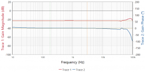
OK, let me clarify what I meant. The attached is the way I assume this is done. Hence my conclusion that the xformer doesn't really figure in the measurement.
Not sure what the best cal method would be; I would connect ch1 to ch2 and cal so that the difference is zero.
Jan
Not sure what the best cal method would be; I would connect ch1 to ch2 and cal so that the difference is zero.
Jan
Attachments
- Status
- This old topic is closed. If you want to reopen this topic, contact a moderator using the "Report Post" button.
- Home
- Design & Build
- Equipment & Tools
- The Bode-100 thread