The idea is interesting, but as described it would make the spreader transistor VCE and thus the initial idle current too HIGH until the capacitor charged. Such a capacitor should go between the base and collector to make the spreader voltage come up slowly. Also, this uses the transistor's gain so the cap value could be much less than the hundreds of uF used across emitter and collector.
Howard,
Don't you worry about the current through the bias spreader. During a positive going clip, it can never carry more than 6mA because of current source Q7.
In the negative it can be completely shut off, that's it's full range is going from 6mA to 0mA.
So, clipping will never be able to destroy the bias spreader, you have the .asc file so it will be easy to check my words when you add the current protection circuitry.
I haven't looked at the relay in your LS output line, but it could very well also serve as a delayed switch on.
But a simple test would be to switch your amp with speaker connected and check what happens, I can't imagine that Luxman overlooked this switch-on aspect.
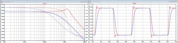
Coming back to the 47pF on Q4, see attachment below for the BJT's that were used.
On the left the FR for resp 47P in red and 1nF in blue and on the right a square wave response.
Hans
Don't you worry about the current through the bias spreader. During a positive going clip, it can never carry more than 6mA because of current source Q7.
In the negative it can be completely shut off, that's it's full range is going from 6mA to 0mA.
So, clipping will never be able to destroy the bias spreader, you have the .asc file so it will be easy to check my words when you add the current protection circuitry.
I haven't looked at the relay in your LS output line, but it could very well also serve as a delayed switch on.
But a simple test would be to switch your amp with speaker connected and check what happens, I can't imagine that Luxman overlooked this switch-on aspect.
Coming back to the 47pF on Q4, see attachment below for the BJT's that were used.
On the left the FR for resp 47P in red and 1nF in blue and on the right a square wave response.
Hans
Attachments
Sorry for the confusion, I meant between base and collector.Wouldn't it be better to insert a Cap between bias spreader's base and emitter to get a slow start ?
Hans
Hans
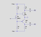
There's one mistake with that M4000 Vbe spreader, the trimmer viper is connected to the wrong side, that is, if the viper or some of the other trimmer legs of some reason, such as bad solder, mech failure etc., would go loose the bjt will see a lower voltage on its base leg and hence will increase the bias voltage, that in turn starts to fry the output transistors as the current bias goes up.
So preferably connect it as in the pic attached here, the fixed resistors values connected to the trimmer may need some rearrangement too to get the bias correct.

So preferably connect it as in the pic attached here, the fixed resistors values connected to the trimmer may need some rearrangement too to get the bias correct.
Last edited:
Thank you Hans,Howard,
Don't you worry about the current through the bias spreader. During a positive going clip, it can never carry more than 6mA because of current source Q7.
In the negative it can be completely shut off, that's it's full range is going from 6mA to 0mA.
So, clipping will never be able to destroy the bias spreader, you have the .asc file so it will be easy to check my words when you add the current protection circuitry.
I haven't looked at the relay in your LS output line, but it could very well also serve as a delayed switch on.
But a simple test would be to switch your amp with speaker connected and check what happens, I can't imagine that Luxman overlooked this switch-on aspect.
Coming back to the 47pF on Q4, see attachment below for the BJT's that were used.
On the left the FR for resp 47P in red and 1nF in blue and on the right a square wave response.
Hans
Was that last sweep with a 610 ohm in place of the 390 ohm for R4?
I'll sweep the amp when it is back together and verify...and replace the 47 pF with a 1 nF if indeed the response is peaked up above 1 MHz , I mean, my hearing is OK to 80kHz or so, but that peak at 1.5 MHz would bother me...ahem lolol Luxman only spec the amp from 3 Hz to 100 kHz +/- 1 dB.. Fortunately those caps are on the driver boards which plug in, unlike the output modules which are a bear and a thermal compound mess to disassemble/assemble:
I really appreciate you lending your expertise to this issue, I've learned a lot!
Cheers,
Howie
Thanks for the tip, I had already changed the bias pot to a Bournes sealed cermet 4-turn pot. The footprint was different so I had to choose a new place to land the wiper, so I tied it high. I find these pots to be extremely reliable, and the multiple turns makes setting bias trivial. When I pulled the old pot off the board I attempted to measure it, but I had to turn it around a bit to get a stable resistance measurement so I think it was intermittent from age...maybe this is what caused the one channel to fail? I'll never know.There's one mistake with that M4000 Vbe spreader, the trimmer viper is connected to the wrong side, that is, if the viper or some of the other trimmer legs of some reason, such as bad solder, mech failure etc., would go loose the bjt will see a lower voltage on its base leg and hence will increase the bias voltage, that in turn starts to fry the output transistors as the current bias goes up.
So preferably connect it as in the pic attached here, the fixed resistors values connected to the trimmer may need some rearrangement too to get the bias correct.
View attachment 1151651
Cheers!
Howie
Yes, this was with R4 = 610 Ohm, but this value has no effect on FR, only on distortion.Thank you Hans,
Was that last sweep with a 610 ohm in place of the 390 ohm for R4?
I'll sweep the amp when it is back together and verify...and replace the 47 pF with a 1 nF if indeed the response is peaked up above 1 MHz , I mean, my hearing is OK to 80kHz or so, but that peak at 1.5 MHz would bother me...ahem lolol Luxman only spec the amp from 3 Hz to 100 kHz +/- 1 dB.. Fortunately those caps are on the driver boards which plug in, unlike the output modules which are a bear and a thermal compound mess to disassemble/assemble:View attachment 1151676
I really appreciate you lending your expertise to this issue, I've learned a lot!
Cheers,
Howie
When you measure the voltage over R4 and R11, you should be able to calculate that R4 carries twice the R11’s current.
Be aware that the shown FR and square wave respons are taken before the output filter.
At the LS output things are different.
When you want me to run the same sim at the LS output, let me know.
Hans
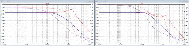
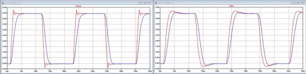
It may be revealing to see the differences in response between before and after the output filter, these two signals resp called V(out) and V(LS), making it easier for you to choose which of the two you are going to measure.
Below again red for 47pF and blue for 1nF for C3, left plot for V(out) and at the right for V(LS) as can be seen in the above superscripts.
Hans
Below again red for 47pF and blue for 1nF for C3, left plot for V(out) and at the right for V(LS) as can be seen in the above superscripts.
Hans
Attachments
Mark Levinson uses a circuit in all their amps right from the beginning to shorten the Bias voltage generator with the circuit in the attachment.My use of high capacitance as bias spreader comes from thump suppression at amplifier turn-on.

At power-on the mosfet is switched slowly into conduction after ca. 30 seconds and goes immediately in non conduction at power down.
Through P6 and P7 both sides of the the bias generator will be connected to gnd, effectively preventing the unwanted thumbs.
Hans
Attachments

I want to thank everyone who took the time to discuss this bias system. I regularly use the Cordell and Self books, not to mention Nelson Pass and John Curl's writings to help understand amplifier systems, but none of the above I could find went into any detail regarding bias bypassing...
Thanks especially to Hans Polak who did the heavy lifting actually simming. So generous and much appreciated! I will report back with AP graphs of the final result when I get all the parts to assemble these amps.
Cheers!
Howie

Thanks especially to Hans Polak who did the heavy lifting actually simming. So generous and much appreciated! I will report back with AP graphs of the final result when I get all the parts to assemble these amps.
Cheers!
Howie
Last edited:
Thx Howard,
It’s always a pleasure to assist peolpe who can appreciate it.
Looking forward to see your AP graphs.
Hans
It’s always a pleasure to assist peolpe who can appreciate it.
Looking forward to see your AP graphs.
Hans
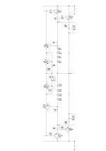
Further to the discussion started by Howard, "what cap magnitude on a bias generator", it's interesting to see that Mark Levinson developed a simple bias circuitry called adaptive biasing, see attachment.
This bias system prevents that one output halve gets shut off while the other halve is heavily loaded.
This effectively prevents any crossover distortion, while not needing absurd amounts of bias current to keep both halves conducting, like needed for Class A.
But interesting to see is that they do not even use a cap on the bias generator, the one that Howard was looking for.
So apart from thump correction that Nelson mentioned, you won't really need a cap at all.
Hans
Attachments
Ian Hegglun has very similar in Towards a wideband non switching Auto Bias power amp....bias system prevents that one output halve gets shut off while the other halve is heavily loaded...
Hi Indra, I may have overlooked it, but going trough the thread it gradualy came close, but what I still missed was the trick with the diodes which was very essential to keep it working without crossover for any load and independent of temp.
Hans
Hans
Here is what he did on a live bench test.I still missed was the trick with the diodes which was very essential to keep it working without crossover for any load and independent of temp.
Another development is the thermal feedback from the Schottky's to the autobias spreaders. Q1 and Q3 are mounted on the Schottky's and Q2, Q3 are left at ambient. This halves the effective temp.co for the spreader and about the required compensation as the Schottky's heat up (from turn on and then when run at full power). The BD139-140 packages were mounted on the top end of the TO-220 Schotty's metal tab with a thermal washer, and two TO-220's were mounted on a small metal plate (2cmx3cm) separate from the main heatsink. The response time was quite fast with a slight undershoot after running hot. Using only one spreader transistor for compensation per slice worked much better than using a PCB thermal washer to drop the temperature from the Schottky's which created a huge undershoot after running at full power.
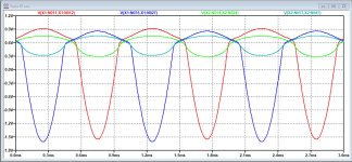
Indra, I'm not sure to what circuit diagram you are pointing, but to make the advantages of adaptive biasing more clear, I have simulated the Vbe voltages on the output transistors for two amps.
First a ML No.20.x delivering 100Watt in full class A into 8R, equipped with a conventional bias spreader.
Second a ML No.33, being the No.20.x's reference successor, having the same bias current setting as the ML20.x but now with an adaptive bias circuit.
When both driving a 2R load, class A rapidly ends when one halve has to source lots of current far beyond the bias current.
That's why for this example, I've let both amps drive a 2R load at 25V rms.
What can be seen in the first attachment are the Vbe voltages in Red and Blue for the No.20x's output transistors and in Green and Teal the same for the No.33.
For the sake of easier reading, I have inverted the negative PNP Vbe voltages.
It's quite obvious that the 20.x's output trannies are confronted with a deep reversed bias voltage when the other halve is conducting, in this case even as much as 1.6 Volt peak.
The 33 with its adaptive biasing , see second attachment, shows that thanks to the diodes CR4-CR8 and CR105-CR109, the output transistors in this example still keep at least 0.3 Volt Vbe, not much, but enough to prevent the dreaded crossover spikes.
Hans
Attachments
You can see Post #138 I referred, but you can also access that if you click the header of quoted post.not sure to what circuit diagram you are pointing
Last edited:
Just wondering if there is any thought as to performing listening tests comparing two identical amplifiers, except one with a traditional well implemented Vbe multiplier bias spreader, and the other with this sort of adaptive approach?
Reason for asking is that IIUC sometimes similar clever ideas that have looked good in sims, and maybe even under steady-state testing with a resistive load, don't always perform as well as expected under dynamical music conditions with a more difficult speaker load.
Not saying there would be any problem with this circuitry of course. Don't know. Just wondering how it might work in practice with real music and real speakers 🙂
If you want to do AB tests, one of them should be allowing the tester to use the switch to apparently change things but actually always be the same amplifier and see what the reported differences are. I actually have had real differences show up! I don’t use that brand of switch anymore.
- Home
- Member Areas
- The Lounge
- The Black Hole......