Mark, I don't imagine that I would ever fault you.
And to be fair, the application on the patent was earlier than my article.
🙂
And following this path, in 2002 Cyril came with his paper, going in the greatest possible depth clearly showing that the magnitude of the positive reflection coeff. was the cause of frying amps
And like you who also found the solution, with proper termination at the LS side, this problem can be completely cured.
Cyril even came with a nice DIY reflection measurement tool to determine with the help of a scope the optimal termination for a specific cable + LS combination.
Hans
Well here is the result of my foray into EPDR:
Calculating EADR (similar to EPDR) | Audio Science Review (ASR) Forum
It's a fun story I guess. I thought about posting it here too.
Thank you for sharing your view on this EPDR topic.
I think that looking at average or peak power is only part of the story.
Exceeding the Soa line may result in a catastrophe at whatever power level.
To my opinion an amp rated for some power, should be able to produce this power over the whole audio range up to 20Khz,
Using the ML23.5 again as an example, this amp is specified for 600Watt@4R, which results in 70Vpk on the speaker.
With a resistive load this can be achieved trouble free.
However already when lowering the output voltage to 60Vpk in series with 50u, the Soa line will be exceeded.
Reducing it's Vsupply to 70Volt, and feeding the speaker with the same 60Vpk, the consumed power in the output transistors is back within the Soa.
I suspect that this could be the reason why the ML smaller brothers with lower Supply voltages are blown much less as this powerful version.
No EPDR or EADR could have told this.
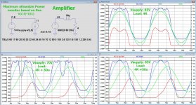
See images below,
First the measurement setup generating 60Vpk to resp. two versions with Vsupply 85V and one with Vsupply 70Volt.
The blue line is the maximum allowable power according to the Soa.
The red line shows the power consumption in the amp's positive halve, V(C-E)*I(x1:R44), where R44 is a 0.1R resistor between the LS output and the positive halve.
The green line shows the current through the load, in this case I(R20).
Hans
.
Attachments
Douglas Self covers Zobels in great depth in his books and his amplifiers include them. And still the late Cyril Bateman blew one up.The net effect is that amps that omit these critical parts (and usually demand use of their own cable) can indeed oscillate and self destruct when the inductive output impedance resonates with the cable capacitance. But that is down to inadequate amp design, not the cable.
Don't worry, we have all accidentally swallowed the audiophile coolaid at some point. Admission is the first step to a cure though 🙂FWIW I use woven cable (Kimber)
That is certainly one of the benefits of interleaved wires. A minimal intercept loop is minimization of any coupling from external em fields.The main effect of low inductance is to minimise environmental RFI pickup, which itself is an issue if it gets into the feedback loop of a power amp.
Another is the taming of settling time.
So, 15 ohms rfz. So, either 6 or 7 wires per leg, assuming reasonable insulation.FWIW I use woven cable (Kimber) with my multichannel amps for my active crossover speakers (LS521) without any problem whatever. But they have Zobel and inductor fitted. Kimber 8TC has 346pF/m capacitive and 0.08uH/m inductive.
jn
Thank you for sharing your view on this EPDR topic.
I think that looking at average or peak power is only part of the story.
Exceeding the Soa line may result in a catastrophe at whatever power level.
...
I suspect that this could be the reason why the ML smaller brothers with lower Supply voltages are blown much less as this powerful version.
No EPDR or EADR could have told this.
Yes, EPDR and EADR only really apply when the amplifier is operated within it's limits. Because SOA is so variable between amps and transistors, you can't make a general curve like "ESOAR" that would apply to any amp. The best you can do is make a curve that correlates with amplifier lifetime when not overdriven.
I suspect SOA calcs need to include at least three frequencies for a three way speaker, as the drivers present as parallel for a complex waveform.
A simple l/r/c load model is great when only one driver is involved.
Jn
A simple l/r/c load model is great when only one driver is involved.
Jn
Douglas Self covers Zobels in great depth in his books and his amplifiers include them. And still the late Cyril Bateman blew one up.
Funny, Nelson Pass wrote the 1980 article, 22 years before Bateman, AND his amplifiers don't include Zobels which Bateman insists are mandatory, AND his amplifiers don't include output inductors which Bateman insists are mandatory, AND neither Bateman nor anybody else has managed to blow up a Pass amplifier by connecting a "difficult" speaker cable. Let us now draw some conclusions?
_
Last edited:
Funny, Nelson Pass wrote the 1980 article, 22 years before Bateman, AND his amplifiers don't include Zobels which Bateman insists are mandatory, AND his amplifiers don't include output inductors which Bateman insists are mandatory, AND neither Bateman nor anybody else has managed to blow up a Pass amplifier by connecting a "difficult" speaker cable. Let us now draw some conclusions?
_
Mark,
Bateman also mentions that tube amps aren’t prone to this cable problem.
And just because he found the first indications of things going wrong with a differential probe at the input, it points in the direction that the amount of loop gain might be a vital ingredient in this problem.
Without global feedback it seems impossible to get this oscillation on the input and an output inductor also seems totally superfluous in that case.
And when it is correct from what I have read, Pass tries to avoid using large amounts of global feedback as is also the case for (most) tube amps.
When true, it explains the different views on needing Zobels and output inductors depending on the used topology.
Hans
I suspect SOA calcs need to include at least three frequencies for a three way speaker, as the drivers present as parallel for a complex waveform.
A simple l/r/c load model is great when only one driver is involved.
Jn
You need to run Ice(Vce) plots with instantaneous (=peak) values for the whole frequency range. Frequency stepping in a simulator makes it easy. Time plots like I(t), P(t) do not make much sense in SOA safe area answers.
Attachments

Last edited:
Pavel,
Sorry, but I have a problem understanding your plots and hopefully I'm not the only one.
To start with I see a reference to Q35 and R35, but just like R35 there is no Q35 in your circuit diagram, so this should possibly be one of T1 to T4, ?
Then you mention that Time plots like I(t), P(t) do not make much sense in SOA safe area answers., could you elaborate what you mean by this ?
But seemingly in contradiction with this your plots are Time Plots from zero to 30 msec, so how exactly should these plots be read, I tried hard but I didn't get it.
Hans
Sure,u if you just plotted worst case expected load phase angle at or close to full power you would cover all frequent cases?
On a sine wave, there are 4 dissipation peaks per cycle. You can also plot a classic SOA over 0-90 degrees against a reactive load to see if you are in SOA limits.
On a sine wave, there are 4 dissipation peaks per cycle. You can also plot a classic SOA over 0-90 degrees against a reactive load to see if you are in SOA limits.
In the Pro world one manufacturer used to test their designs using a load of just a very high power 70 volt transformer. It was Basically all inductance, with a little bit of resistance. They would adjust their protection circuit values to prevent failures. If driving capacitive loads they suggested using an external resistor.
Another manufacturer would send out beta test amplifiers to major users. If they got failures output transistor pairs were added until they stopped seeing failures.
A third manufacturer as far as I know actually designed for SOA considerations.
One minor player just copied the designs of others, but used what they considered better components.
More relevant adventures far beyond my depth:
Calculating EADR (similar to EPDR) | Audio Science Review (ASR) Forum
Calculating EADR (similar to EPDR) | Audio Science Review (ASR) Forum
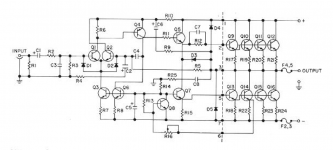
I attach below a zoomed-in schematic of a DIY amp that Pass published in Audio magazine, Feb 1977. archived copy... [Bateman's 2002 paper] points in the direction that the amount of loop gain might be a vital ingredient in this problem.
Without global feedback it seems impossible to get this oscillation on the input and an output inductor also seems totally superfluous in that case. And when it is correct from what I have read, [Nelson] Pass tries to avoid using large amounts of global feedback as is also the case for (most) tube amps. When true, it explains the different views on needing Zobels and output inductors depending on the used topology.
There's lots of gain and lots of feedback, with a conventional 1977 LTP IPS, a conventional 1977 CE VAS, and a conventional 3EF OPS (with bias current increased to give Class-A operation). There is no Zobel, and no output inductor, and no reports of amplifiers destroyed by misbehaving speaker cables.
R5 = 4700 , R4 = 470
_
_
Attachments
That is certainly one of the benefits of interleaved wires. A minimal intercept loop is minimization of any coupling from external em fields.
Another is the taming of settling time.
So, 15 ohms rfz. So, either 6 or 7 wires per leg, assuming reasonable insulation.
jn
It is 8 per leg. And that characteristic impedance is about right.
Douglas Self covers Zobels in great depth in his books and his amplifiers include them. And still the late Cyril Bateman blew one up.
Don't worry, we have all accidentally swallowed the audiophile coolaid at some point. Admission is the first step to a cure though 🙂
Indeed the late great Bateman blew a Self Blameless up. But it was the original design that appeared in Wireless World. The design went through at least two iterations following that, and the latest Blameless (which is what I have ten channels of for the LX521) has not missed a beat in 8 years. It is those later designs that appear in the last two editions of Self's power amplifier book.
The reason for 8TC is that I am running five wire pairs (two woofer, lower mid, upper mid and tweeter) in the same techflex. Using woven cables, there is minimal interaction between each pair, since the external field from a woven cable is quite close to zero (and yes I have measured it up to 50kHz feeding 6A into the cable and measuring induced voltage across a sensing wire) . So nothing to do with audiophile nonsense - just practicality.
I attach below a zoomed-in schematic of a DIY amp that Pass published in Audio magazine, Feb 1977. archived copy
May I ask what is the voltage at the +/- DC rails for 8 Ohm load?
George
- Home
- Member Areas
- The Lounge
- The Black Hole......