Sorry, formulae were the other way around. Thank you for pointing that out (early on 🙂)George,
You are getting scary
I inserted a correction in my post .
For the rest, I don’t see a disagreement.
And the DMM guys average over one quarter of the signal period, so the Vavg is non-zero for a sinusoidal signal balanced around the zero line.
Now, I am certain you check in your shop the specs of PAs on a regular basis.
What kind of numerical read-out instruments do you connect (in parallel to an analogue oscilloscope 😀) at the output of an amplifier when you evaluate the actual power output vs specs? Are they of the 0.707*Vp kind or are they of the 0.638*Vp kind?
This was my initial question.
Yes Scott, thank you
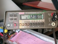
Only to mention that it’s not the price of the instrument that dictates what kind of measurement it makes. I have here a Keithley bench DMM that (at it’s time it) was expensive, yet it’s not a true rms instrument. At the specs it says AC VOLTS, AC AMPS (average responding).
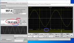
Then they are the Digital Oscilloscopes which display numerical data along with the waveform.
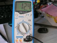
A very cheap hand held one I have here, displays correctly the Vpp and it displays the Vrms as well. Only that I double checked it today (*) and the Vrms it displays is actually Vavg.
(*) I used it to do some measurements that I posted on another thread two days ago. I rechecked the measurements there and the numbers didn’t add well. 😀😱
George
Attachments

You’ve stated your recommendation here, thank you Ed.Are they of the 0.707*Vp kind or are they of the 0.638*Vp kind?
I suspect you are interested in measuring an amplifiers power output, so the RMS value is more useful. As a practical matter, if you are testing using sine waves, a peak reading but RMS value displaying meter is fine
I really don't know of any practical use for the average voltage reading of a half sine!
George
here are several implementations of ac to readout reanging from a simple acreage responding RMS indicating analog meter (simple and adequate for low distortion since waves) to thermal converters and the Keysight sample and calculate solution. The last two are very accurate at a huge premium.
Also important is what you are measuring and why. Power into a resistor wants true rms to know the heating power. AC into a rectified power supply is quite different and you care about the peak voltage of which the RMS meter won't give you a proper reading on a distorted sine wave like most power service. The peak reading average responding meter will show the actual supply voltage however (after the appropriate conversions).
If you are measuring sine waves to confirm amp power output any of these meters should indicate the same. The error increases as the distortion increases but if the amp is distorting the sine wave then its probably not inside its operating range.
Audio program is quite another issue and needs different ways of checking again for different applications. Its why you have PPM meters and VU meters both with defined ballistics to indicate short peaks.
George,
I use a Fluke Model 87. It is true rms. A friend tested it on pink noise and determined that as long as you stay below 30% of full scale it is accurate.
A .707 of peak reading meter is fine for sine wave power testing. I would not use it with multitone tests.
.638 is as far as I know of no applicable use.
As to Demians' comment on measuring power supply rails, I always check those with an oscilloscope. What happens with a transformer changing the AC voltage and the power line harmonic distortion, the actual rail voltage is usually wierd.
One fun issue around here is some smaller transformers are rated for an AC primary of 110 or 120 VAC. As the line voltage is often higher, they see some saturation and thus deliver a more constant secondary voltage but with more distortion. So they appear to have better regulation even with thin wire and small cores. They just heat up a bit more, which is not usually an issue with small stuff.
Last edited:
Nowadays, most DMM's do true RMS thanks to the compute type RMS-to-DC chips that go for a buck a piece.
The real problem is: most DMM's are good to 400-1000 Hz only; that's why I keep maintaining my HP 3400A: thermocouple, chopper amp, the works.
The real problem is: most DMM's are good to 400-1000 Hz only; that's why I keep maintaining my HP 3400A: thermocouple, chopper amp, the works.
Nowadays, most DMM's do true RMS thanks to the compute type RMS-to-DC chips that go for a buck a piece.
The real problem is: most DMM's are good to 400-1000 Hz only; that's why I keep maintaining my HP 3400A: thermocouple, chopper amp, the works.
Yep, on the bench I use a HP 34401A up to 20 KHz or so, it is rated +/- 0.05% from 5 Hz to 20 KHz and +/- .6% to 100 KHz.
I may be old fashioned, but I trust my HP400EL, it is rated +/- 1% 10 Hz to 2 MHz and thanks to it's mirrored scales you can do relative comparisons to 0.1%. It is one of the most reliable pieces of test gear I have ever used and I have dragged it everywhere for 3 decades. I sent it for calibration in 2000 and after a decade of hard road use it was still fully in spec...there is something about that meter that inspires confidence...
I return you this thread out of the OFZ.
Howie
When solder solidifies, it's volume decreases about 15 percent. This builds huge strains, low cycle fatigue wipes that out big time. This was a big concern with on the pole parts where daily temp cycles killed the joints. IBM a long time ago setup a wave soldering system using bismuth fraction alloy, it freezes without shrinking.Yes there were a bunch of processes that weren't as good as they could be and this shows up in joints that are contaminated crystalline and thin to start with and crack around the pcb hole with thermal cycling transport etc sooner or later.
On a house gas fired heating system, such as a Weil McClaine gold unit, the pcb is at the top directly under the hood, and the larger soldered pins end up with cracks completely around the copper pins.
Reflowing the joints is imperative. Wicking the old and using a good flux totally restores the board.
Jn
I have done nothing on that. Quite honestly, I have no desire to even think about it, for reasons I would prefer not to discuss.Hey, JN! We've not heard from you for a while... How are you - how's all the speaker projects?
I am building a nice toroidal winder, but my work at home laptop has no SD card reader, so I cannot post pics of the really excellent, fantastic, utterly incredible things I am doing with it...well, ok, that's really pushing it...but I can't even post pics of all the really stupid things I've tried and revisited, that list is looong.
I am getting good experience with my mill and lathe... oh, while working the mill I found it was 15 mils per inch out???? Turns out, the dro setup was set to 5000 counts per inch, it was supposed to be 5080 CPI.
As to technical discussions on this thread, I'm pretty much done here.
Thanks for asking.
Jn
Some cheaper mfrs used contaminated solder that formed bubbly and crystalline looking joints guaranteed to fail under heat cycling.When solder solidifies, it's volume decreases about 15 percent. This builds huge strains, low cycle fatigue wipes that out big time. This was a big concern with on the pole parts where daily temp cycles killed the joints. IBM a long time ago setup a wave soldering system using bismuth fraction alloy, it freezes without shrinking.
Another recipe for failure was component lead ends trimmed or ground after soldering leaving ready path for corrosion failure.
Another recipe for failure is plated brass rivets and connector pins where the solder looks to have 'unwet' from the pin this failure mode is caused by inadequate solder time and temp at assembly as hand reworking cures the issue long term.
The world is full of such engineering mistakes that could be readily avoided.On a house gas fired heating system, such as a Weil McClaine gold unit, the pcb is at the top directly under the hood, and the larger soldered pins end up with cracks completely around the copper pins.
Reflowing the joints is imperative. Wicking the old and using a good flux totally restores the board.
You would be appalled how many amps die (or are about to die) because one joint of the bias monitor transistor cracked and went open sending OPS bias current high enough to melt OP transistors.
Some mfrs hand solder those three joints after mounting heatsinks some don't and are the first three (six) solder joints to make sure of at service time.
Last edited:
... It is one of the most reliable pieces of test gear I have ever used and I have dragged it everywhere for 3 decades. I sent it for calibration in 2000 and after a decade of hard road use it was still fully in spec...there is something about that meter that inspires confidence...
...Howie
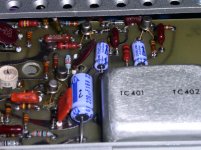
I'm not as lucky; about 10 years ago, I had to replace all the electrolytics (lots of them!) and the nuvistor (with a JFet!). In the attached pic, all the blue stuff are my doing. Overall, the way the thing was built makes me think of a ... transistor radio. There goes the century old debate of HP vs Tek; and I'm a Tek guy 🙂.
Attachments
Last edited:
It's good practice to replace all the electrolytic caps in any piece of electronics every decade or two, especially test equipment. Like car tires and batteries, just operating costs.
If anybody ever gets to travel again, the Tektronix museum just west of PDX is worth the visit. It's small, very large living room size, but full of cool stuff and interesting docents. If you think this thread is geeky, you haven't met these guys yet. Ask about the nuclear bomb scopes.
All good fortunes,
Chris
JN,
We could talk about machine tool setup. If you don't already have one a straight edge or six are quite useful. Very easy to obtain as McMaster Carr and many others sell precision ground bars. A 3' length of 2" x 1" should do most set ups and tests on a milling machine. A 4" x 1" x 1/8" is handy for a small lathe.
Of course you will need some high spot blue for really precise tests.
Then we can talk about an accurate machinists level. Best bought at a garage sale as new they are a bit pricey. You can get replacement vials for them. But as a true DIY you can use a bit of precision ground stock and make your own.
Next up is a precision square, not very expensive these days and you can test it with two pieces of ground stock and a level.
I don't think you will need a granite block, but I did find one that was quite affordable and reasonable small and light (70 lb.)
Next up would be a drill centering gauge, just a few bucks.
With a lathe most folks these days use micrometers, dial indicators or even DROs. The old guys would make their own calipers and use an engraved ruler. I do have a few interesting calipers. Some look like a pair of legs. You can guess what a guy would model the legs on!
I also have made my own set up blocks for my press brake. I made front and rear tables with 1/4-20 tapped holes on a 1" grid. I then have pieces that fit in the holes and have edge lengths that vary in 1/16" intervals. That was the method used before DROs and adjustable back stops.
Of course things like tread gauges and shim sets are also handy.
My long term current project is rebuilding a pair of surface grinders. I only wanted one, but ended up with two. WWII surplus, but the current Chinese copy sells for better than $3,000.00! I got both for $140.00. All I need to do is use high spot blue, a straight edge and patience with a stone to get them back to like new. Will look even better repainted.
Last edited:
Just for fun one could level a granite plate with just a few wedges and a bit of water. Then run a plumb bob just off one edge and use the setup to check and adjust DIY squares. Add a candle for really precise adjustments.
Fortunately you don't have to grind your own flat plate these days. Wonder if ice would work?
Fortunately you don't have to grind your own flat plate these days. Wonder if ice would work?
It provides light to show the gap. The candle goes on the far side of the square and you look through the cap to the candle. If the gap is uniform then things are square. If it is wider at top or bottom then you know how it needs to be adjusted.
Some precision squares will require honing or if really off grinding. For a carpenter's sheet metal square you use a center punch and hammer.
Last edited:
At some point I will trammel my mill, get it to under a mil per 10 inches. But it is just fine for me at the moment at 1 mil per inch.
I do have one R8 collet that refuses to mount, the back end is .0005 inches too large in diameter. When I need .250 capability, I'll probably chuck it in the lathe and hone it down. Mixed processes I know, but it gets the job done. Blued it to see where it is interfering.
What bugs me now is the Jacobs is .003 runout, that's driving me nuts.
Looks like that Youngswood gig will happen, I'll let you know.
Jn
Max P..
Unwet.... the options are no wetting and dewetting.
No wetting:
Metals other than copper many times require a different chemistry flux. It's possible to get away with one as long as it can activate the surfaces within the required temp range.
Dewetting:
The act of first wetting, and then not wetting. Standard soldering produces two copper tin alloys layered between the copper and the solder. I have seen many copper parts that by machining or forming, have oil and other contaminants embedded within the metal. During soldering, this comes out of the metal and passivates the upper layer of copper tin alloy. Then, the solder will no longer adhere. This will require an RMA flux to break through.
This is actually one of the problems that caused the CERN explosion. They had both machined and formed copper parts in their interconnects, and could only use R type flux.. they had no idea their piece parts failed solderability.
Jn
I do have a few interesting calipers. Some look like a pair of legs. You can guess what a guy would model the legs on!
Oh, you "just gotta" post a picture of those. My dad was a GE apprentice machinist graduate in the late 40's - I still have a few of the things he made in that course - but nothing like that!
And where should one put said candle?
Well, at work we mount plates onto our mill bed with molten wax, low stress and effective on thin materials without imparting and deformation (like the masking tape and superglue trick can do).
Then again that's for precision microfluidic devices, so not exactly relevant here 😉
George -- if you wanted to calibrate a true RMS, what sort of precision are you hoping for? Wouldn't a soundcard and amplifier across a resistor work?
Last edited:
I may be old fashioned, but I trust my HP400EL, it is rated +/- 1% 10 Hz to 2 MHz and thanks to it's mirrored scales you can do relative comparisons to 0.1%. It is one of the most reliable pieces of test gear I have ever used and I have dragged it everywhere for 3 decades.
My first decent multimeter was HP3435A. It's approaching 50 years on my
bench, and is still my favorite.
- Home
- Member Areas
- The Lounge
- The Black Hole......