I've been looking for a way to measure and characterize noise on power supplies and amplifier outputs. Unfortunately, a good FFT spectrum analyser is expensive.
But a computer sound-card based FFT would be all I need. I'm only interested in the audio band. But the noise signal on the output of an amplifier is tiny; in the sub-millivolt range. It's hard to get meaningful measurements. What's needed is a super-quiet pre-amplifier, to feed the sound card. To elevate the noise above the noise!
TNT Audio covered this...
Simple Voltage Regulators Part 1: Noise - [English]
I'm looking to do the same, so I need to build a pre-amplifier.
Design goals:
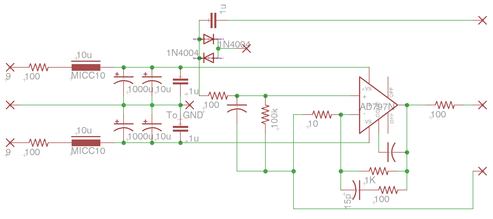
I figured the AD797 would be the ultimate choice for such a task. I'm sure it's overkill in the extreme, but that's good. The circuit reflects some of the recommendations in the datasheet, such as the use of very low resistor values (it can push 30ma), and the feedback resistor compensation.
I do not have a background in low-noise preamplifier design, so any comments are welcome. I want to make this as good as it can be, and useful in lots of ways.

If this works well, maybe it could become an item in the DIYAudio Store?
But a computer sound-card based FFT would be all I need. I'm only interested in the audio band. But the noise signal on the output of an amplifier is tiny; in the sub-millivolt range. It's hard to get meaningful measurements. What's needed is a super-quiet pre-amplifier, to feed the sound card. To elevate the noise above the noise!
TNT Audio covered this...
Simple Voltage Regulators Part 1: Noise - [English]
I'm looking to do the same, so I need to build a pre-amplifier.
Design goals:
- Ultra low noise
- Low disortion
- Battery powered (9V x 2)
- RCA and BNC inputs and outputs
- Configurable gain resistors using pin-sockets
- Configurable compensation caps using pin-sockets
- Small and portable
- Well shielded
- Usable as a general-purpose audio line amp, maybe even mic preamp
- Switchable diode-clamp DC protection on input for measuring power supplies
I figured the AD797 would be the ultimate choice for such a task. I'm sure it's overkill in the extreme, but that's good. The circuit reflects some of the recommendations in the datasheet, such as the use of very low resistor values (it can push 30ma), and the feedback resistor compensation.
I do not have a background in low-noise preamplifier design, so any comments are welcome. I want to make this as good as it can be, and useful in lots of ways.
If this works well, maybe it could become an item in the DIYAudio Store?
I do not have a background in low-noise preamplifier design, so any comments are welcome.
I want to make this as good as it can be, and useful in lots of ways.
Use a ground plane, for starters.
Well, I have read that in analog designs, ground planes can actually cause more problems than they solve, with stray capacitance coupling things that should not be, though I don't think that would be an issue here. But there's no transformer to be shielded from in this design, so I thought it might be better without.
Further refinements... I was missing a drain resistor on the input cap, which could be a big problem considering I'll be testing power supplies and the cap could be charged to 85V.

If I remeber well there is an application note from Linear Technology that treat this subject very very well.
The application note propose a circuit to be powered by batteries and add an active filter in output.
I am sorry but I am off of my lab and I don't remeber well the application number
The application note propose a circuit to be powered by batteries and add an active filter in output.
I am sorry but I am off of my lab and I don't remeber well the application number
I couldn't find the application note you speak of, but I googled "Linear Technology low noise amplifier" and found some really great stuff in the LT1115 datasheet about balancing source currents, information I've been dying for. I'm thinking my approach should be one that prioritizes low resistor values for lowest noise, over balancing the source currents. A small DC offset is a non-issue for the application. Maybe there are other side effects I'm not considering... I'm looking to find them...
Here's the LT1115 Datasheet
Here's the LT1115 Datasheet
I figure the 100R/10uH/1000uF RLC filter on the input should be pretty effective filtering whatever minuscule noise comes from the alkaline batteries, and provide a nice low-impedance local current supply. Maybe 100R is overkill. The Iq of the op-amp is about 4ma, which is like a 3K resistive load. I wonder if I should resistor-pad the smaller filter caps, the 10uF and 0.1uF? To prevent ringing?
Application Note
Phloodpants
The application Note is AN83F attached.
I also give you my implementation of this AN. My circuit was assembled in performed board and work very well until now.
The PCB uses ground plane, but I do not active it to make the evaluation of the board easier.
I hope it help a bit
Regards
Ronaldo
Attachments
I just forgot to mention:
If somebody has some improvement to my circuit, it is very welcome as I do not make industrial PCB for this project yet.
Maybe I can make it in near future if someone is interested.
Regards
Ronaldo
If somebody has some improvement to my circuit, it is very welcome as I do not make industrial PCB for this project yet.
Maybe I can make it in near future if someone is interested.
Regards
Ronaldo
I just forgot to mention:
If somebody has some improvement to my circuit, it is very welcome as I do not make industrial PCB for this project yet.
Maybe I can make it in near future if someone is interested.
Regards
Ronaldo
Wonderful thread-jacking 😉
//
Wonderful thread-jacking 😉
//
Thank you!
I was Ericsson employer for long time and I could visit Sweden some times.
Very nice country
Ronaldo, the board looks wonderful, and your datasheets are admirable.
That thing has a great feature set, and it's construction is very interesting. I'm learning just by looking at it.
It does more than I think I need though. I don't need the band-pass circuitry to do FFTs on a computer.
So, I think it's still worth pursuing this simple, small gain-block thingy.
But I'd buy a board from you if you ever get them made.
Ronaldo, the board looks wonderful, and your datasheets are admirable.
That thing has a great feature set, and it's construction is very interesting. I'm learning just by looking at it.
It does more than I think I need though. I don't need the band-pass circuitry to do FFTs on a computer.
So, I think it's still worth pursuing this simple, small gain-block thingy.
But I'd buy a board from you if you ever get them made.
Thank you very much for your kind words.
I do not plan to make these boards as there is so little interest and they are a little expensive to make and use one or two.
If some one has interest I can provide gerbers. I wonder if I could get 2 boards as I have all the parts.
When I make it I was working in low noise power supply and I put option to increase gain as the project become better. I also put 2 kind of artificial ground circuits, one using special IC and other using NE5532. I could no find diferences in working with both.
It is to be powered by batteries.
Sorry for portuguese description in doc.
As far I know the active filter was fased out.
Last edited:
You can get 10 boards for around $50 at Seeedstudio.com. I use them all the time, and the quality is excellent!
Most instrumentation amplifiers have balanced inputs, which avoid the problems with ground / hum loops that your circuit might have (you have input and output referenced to a common point). How are you going to guarantee that the input under test is not going to interact with whatever is connected to the output (a computer sound card?) through the common point, at milllivolt levels.
The 1uF input coupling / DC isolation cap should have a resistor to common point so that the cap has a discharge path when it is disconnected from the input Device Under Test, eg 100K.
If the source impedance of the DUT is high (above 1~10k ??) its self generated noise will be higher than the AD797, defeating the purpose of using this OTT op amp.
The back to back diodes across the input protect the opamp input from damage, but they limit the max input voltage to just a couple of hundred mv peak, before their gradual turn-on characteristic of the diodes will distort the signal at detectable levels (eg. FFT spectrum of 16 bit ADC).
Dear Glennb
Thank you for your comments.
I saw lots of implementation of this circuit around web. Yes, there was some implementation using instrumentation amplifier as well.
As this circuit is to measure noise totally isolated, shielded and powered by batteries, in my point of view there is no need to use instrumentation amplifier as amplifying device. The idea was to use 3 good Amp Op dividing the gain to get a good bandwidth.
I suppose you propose to add a 1uf in parallel with C15 and C16 to improve high frequency behaviour. I think it is a good idea, but high quality elco capacitor do a good work in that position.
The jFET transistors (BF245A) works as protection and they have some advantages in this position as a very low linkage current.
Remember, this circuit is to be used to measure noise in high performance power supply. The typical output impedance is very low and the noise can be low as some uV. I got arround 7 uV in my old project.
Regards
Ronaldo
Last edited:
Most instrumentation amplifiers have balanced inputs, which avoid the problems with ground / hum loops that your circuit might have (you have input and output referenced to a common point). How are you going to guarantee that the input under test is not going to interact with whatever is connected to the output (a computer sound card?) through the common point, at milllivolt levels.
Hey Glenn, the unit is battery-powered, and the idea is to plug it into a battery-powered laptop with a USB sound card.
The back to back diodes across the input protect the opamp input from damage, but they limit the max input voltage to just a couple of hundred mv peak, before their gradual turn-on characteristic of the diodes will distort the signal at detectable levels (eg. FFT spectrum of 16 bit ADC).
I'm not sure it's the best way, but the idea was to switch these clamping diodes in, only when measuring power supplies, so that the 1uF input cap can charge up to Vcc, without blasting the input of the op-amp. Do you think there would be any leakage current when measuring a typical amplifier power supply? Datasheet for 1n400x says 5uA reverse current, but what about forward current below Vf?
Is there a better way? Something active? Or just low-leakage diodes?
New schematic...

And yes, I was missing the input drain resistor. I think 1M should work fine, but some experimentation is in order.
- Status
- Not open for further replies.
- Home
- Amplifiers
- Solid State
- "The Black Box" instrumentation preamplifier