Thanks for the link, Sidiy. It could help for calculations.
However, I am puzzled with what is required for a full 4th order crossover with notches. This is not as simple I first thought.
The notches used by Hardman or Thiele are asymetrical, they have not the same attenuation at very high and very low frequencies.
Q for symetrical notches is easy to understand, but I feel uneasy with asymetrical ones.
Thiele's patent give details on an active implementation only for a 6th order implementation. A 4th order is sufficient for my purposes.
My questions are, in order to get the lowest response variations :
- what shoud be the shape of the notch (Q ? attenuation at frequencies far form the notch ?)
- what should be the Q of the 2nd order filter ?
forr said:Hi,
I think elliptic filters suited for audio are an interesting step for crossovers just as were the Linkwitz-Riley' 28 years ago..
Here Neville Thiele's patent ....
Sorry, I have very limited technical knowledge - can't help you there - but will say the NTM filters are well worth looking into.
I'm using them in a BSS unit. I'm not as technical minded as you guys, but they _sound_ good.
I don't think this has your answers but has some general info.http://www.bss.co.uk/products/crossoversandlms/fds-366t/docs/NTMFilters.pdf
If you poke around BSS's site you might find additional references -
I'm not sure you can do a fourth order crossover with that method.
For whatever reason, 36db and 52db slopes are the only NTM slopes offered as options in the BSS software - , and there is a wide variety of options.
For those interested in the NTM crossover - Rod Elliot did some experimentation on these as well:
http://sound.westhost.com/articles/ntm-xover.htm
Regards
Charles
http://sound.westhost.com/articles/ntm-xover.htm
Regards
Charles
Hi,
Thanks for your replies. I hope my posts will rise more interest for notched crossovers than before.
Having googled for the subject, I already knew Rod Elliott's and commercial papers sites refering to the Thiele's patent or JAES article.
I already had the Bainter's paper, found after many monthes using Dogpile, and Thiele's patent.
However I lacked references for basics on notched filters and they may help. Lancaster of Horowitz books are far too short on the subject
Lacking the basics, I had the idea that I could simulate some passive 4th order crossovers given with values by Thiele and then try to get the same frequency response with active circuits using op-amps.
After many trials and errors, I obtained encouraging first resultswith mimic figures for Thiele's passive circuits and my half-active or active ones. This exercise had also some self-teaching virtues and I understand a lot more about notches than at the beginning.
I even found a typo error and a slight calculation error in table #5 page 23 of the patent.
"High pass filter (with C3 in series with L1)"
L2 (µF) should be L2 (µH) of course
0.5774 value for C3 is 62.02 µF , I think it should be 60.55 µF.
So my work is on the good way, some results will be submitted soon.
And what about notched symmetrical subtractive phase-accurate active crossovers ?????? :
Regards
Charles
Charles,
How to realize this in actual implementation/circuit, design equations i mean.
NTM type crossover PCB
I recently finished a PCB design for a NTM type crossover - a 4th order plus notch. I used a state variable filter to get the 4th order LP and HP outputs and then added notch sections to the outputs (not Bainter, though). I confirmed the circuit design using TINA and I am ready to order a run of these boards.
I saw your post and am wondering if there is any interest in these from people out there. The PCB I designed has two separate "crossover" circuits on it, so with one board you could do a 3-way system. My design is proprietary, but I could provide a design and component pick list along with the board.
This is an excellent crossover topology and I am not sure why it is not more common in the DIY loudspeaker hobby area...
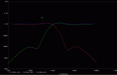
Below is an example of one combination that could be built with the board. The response uses a 4th order Butterworth plus the notch. The 4th order Butterworth response without notch is shown as a comparison:


-Charlie
Hi,
I think elliptic filters suited for audio are an interesting step for crossovers just as were the Linkwitz-Riley' 28 years ago..
Here Neville Thiele's patent :
PAT2PDF - Free PDF copies of patents: Download and print!
I've simulated the Thiele's 4th order passive crossover using Tina.
Crossover at 1000 Hz, notches at 500 and 2000 Hz. The frequency response is very flat.
I then tried to obtain the same results using Bainter's notch,
crossover at 2000 Hz, and notches at 1000 Hz and 4000 Hz.
Despite experimenting with many various values, I could not get rid of response variations, at least 1 dB,
I feel a bit lost with what should be the Q of 2nd order filter section and how to set Bainter's circuit.
Can someone help ?
I recently finished a PCB design for a NTM type crossover - a 4th order plus notch. I used a state variable filter to get the 4th order LP and HP outputs and then added notch sections to the outputs (not Bainter, though). I confirmed the circuit design using TINA and I am ready to order a run of these boards.
I saw your post and am wondering if there is any interest in these from people out there. The PCB I designed has two separate "crossover" circuits on it, so with one board you could do a 3-way system. My design is proprietary, but I could provide a design and component pick list along with the board.
This is an excellent crossover topology and I am not sure why it is not more common in the DIY loudspeaker hobby area...
Below is an example of one combination that could be built with the board. The response uses a 4th order Butterworth plus the notch. The 4th order Butterworth response without notch is shown as a comparison:
-Charlie
Dear All,
Sorrytom spoil the partty: try to load the electric filter transfer functions of both the NT or the Hardman filter with measurements of two 2 real-drivers-in-a-box, and you will discover the combined SPL is all over the place. I tried a re-dimensioning of the Hardman filter in Calsod, with 8th oder target curves. Calsod had a very hard time recalculating the whole thing.. Without acces to SE/Lspcad 6.1/LEAP or other software that can optimize active filters (including Notches) do not even think about these active filters...
It has to be repeated once more: crossover design is about acoustic targets, therefore the actual measured in-box SPL of the driver(s) has to be taken into consideration.
Kind Regards,
Eelco de Bode
Dear All,
Sorrytom spoil the partty: try to load the electric filter transfer functions of both the NT or the Hardman filter with measurements of two 2 real-drivers-in-a-box, and you will discover the combined SPL is all over the place. I tried a re-dimensioning of the Hardman filter in Calsod, with 8th oder target curves. Calsod had a very hard time recalculating the whole thing.. Without acces to SE/Lspcad 6.1/LEAP or other software that can optimize active filters (including Notches) do not even think about these active filters...
It has to be repeated once more: crossover design is about acoustic targets, therefore the actual measured in-box SPL of the driver(s) has to be taken into consideration.
Kind Regards,
Eelco de Bode
What you are saying is essentially correct - that you must also include the driver amplitude and phase in the overall transfer function of the loudspeaker in order to arrive at a good system response. I won't strictly argue that point, but I will say that it is a matter of degree and steeper slope crossovers (up to a point) will have less and less disturbances because the frequency range where overlap between drivers is taking place is smaller as the order increases.
No matter what your approach is, you will need some tools to arrive at a loudspeaker crossover network. What I showed above was only an example of what the SVF+notch could do. As part of the design process for the SVF I use, I can choose the denominator of the transfer function to be whatever 4th order polynomial in s that I want, so I am not limited to "standard" filter types. Because of that, it can be better integrated with the driver responses to get to some overall "acoustic target" (as you say). Additional shaping and delay circuitry will likely be necessary as well.
-Charlie
Thos who can derive transfer functions could adopt a given crossover to a driver. The advantage would be that a minimum of stages is being used.
The other approach would be EQing the drivers. This has the advantage that you wouldn't have to touch the crossover as such.
@ Kanwar: I will have to undig this one.
Regards
Charles
The other approach would be EQing the drivers. This has the advantage that you wouldn't have to touch the crossover as such.
@ Kanwar: I will have to undig this one.
Regards
Charles
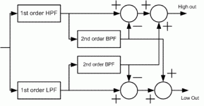
Hi Kanwar
This is the block diagram of the thingie
Regards
Charles
Thanxz Charles,
It looks like interesting topology.
Ignoring 40db low pass
40db low pass - will produce extra signal its-self which is not excepted.
try to ignore above 10db...you can combine 10db several times...
check this out might help u 2-Way Electronic Crossover
40db low pass - will produce extra signal its-self which is not excepted.
try to ignore above 10db...you can combine 10db several times...
check this out might help u 2-Way Electronic Crossover
For design a plate amp module
Hello Friens,
I try to use Precise Xover schematic (Sam post it) in order to build a input + xover module for my speaker cabinet (wich become active). I need your opinion about my draft schematic diagram in pdf attash.
Thank you very much !
Catalin.
Hello Friens,
I try to use Precise Xover schematic (Sam post it) in order to build a input + xover module for my speaker cabinet (wich become active). I need your opinion about my draft schematic diagram in pdf attash.
Thank you very much !
Catalin.
Attachments
For design a plate amp module
I try to use precise xover in order to design my plate amp for my passive speker to become active. I need your opinion about my draft schematic here in pdf. Thank you ! Catalin.
Sam,There have been many threads on active x-overs. I wonder how many of those who have suggested one type of crossover or the other have critically listened to the suggested crossovers versus others. Not to undermine anybody's credibility but a genuine doubt arises when subtractive crossovers are preferred to simpler forms like 2nd order LR.
I have listened to many types of crossovers and orders and have found that each of them are certainly not short of faults. In my opinion the 4th order subtractive crossovers which use All Pass delay networks for linear phase at the output, are the worst sonically. The cut-off profile is nevertheless good and oscilloscope shots leave very little to be desired; however, sonically they cause a blur in the midrange and the transient response plus definition in the bass region is very poor. I think that this is due to higher group delay. The ones that use Low Pass Filters as the active elements before subtraction are the worst offenders.
There are those that use cascaded 1st order High Pass Networks to obtain a 4th order x-over, but the bass suffers quite a bit in these types.
Sometime ago Electronics World published an article entitled "Precise Active X-over". I have referred to this in past threads. I am posting the schematic as an attachment. In my opinion, this is one of the best crossovers sonically. I have configured the orginal two way into three way by duplicating the two way network at the output of the High/Low output. I preferred to tap off the Low output to the Amp, but pass the High output through another two way network to obtain Mid and High outputs. This has been critically tested in domestic environments with highly satisfactory results. The real test for all of the networks mentioned above have been in Professional Audio outdoor work, where 18" drivers are used in Horn-loaded Bass Bins, 12"/10" drivers in Mid Horns and Horn Tweeters are used. The blur in the mids or the slight lack of transients in the bass is all too evident then.
One could improve on the active elements used in the crossover. The schematic shows the NE5532s. I have tested various op-amps including OPA2604s. Each do have a sonic signature. My idea is to try out discrete op-amps, as illustrated in the Passlabs site and use higher operational voltage to avoid a bottleneck after the preamp. The use of low impedance buffers at each of the outputs of the crossover would be a very good idea. Alternative arrangements could be FETs used as followers or the BJT buffers as used by LC Audio.
Perhaps, the one exception to these comments could be the PassLabs Active Crossover which I have not yet auditioned.
This active cross-over is highly recommended for the critical audiophile, especially with refinements to the active elements. The values shown have a nominal crossover frequency of 1500Hz. You can change the frequency by changing the value of all the capacitors leaving resistor values constant.
I try to use precise xover in order to design my plate amp for my passive speker to become active. I need your opinion about my draft schematic here in pdf. Thank you ! Catalin.
Attachments
Hi Charlie, did you find the crossovers satisfactory? I am right DIYing new loudspeakers/amplifierI recently finished a PCB design for a NTM type crossover - a 4th order plus notch. I used a state variable filter to get the 4th order LP and HP outputs and then added notch sections to the outputs (not Bainter, though). I confirmed the circuit design using TINA and I am ready to order a run of these boards.
This is an excellent crossover topology and I am not sure why it is not more common in the DIY loudspeaker hobby area...
-Charlie
- Home
- Loudspeakers
- Multi-Way
- The Best Active Crossover - Here!