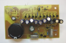
The beast is coming... There's a board, and it's partially stuffed.
Next is deciding what jfet to actually use and match up a bunch. I have 3 choices: J310, J110, or my old friend the PN4393. Schematic will follow when the thing is actually stuffed and running. The concept looks very much like a classic 2-stage SE tube amp, but with a follower in between input stage and output to drive all those gates. The amp will be transformer coupled and run on ~+300V and +30V supplies, just like my "Das ist Aber Schade" and "SiC Pupppy" amps. I'm giving it my pair of 3k 15W Transcendar output transformers - I hope the performance will be worthy of the iron.
Next is deciding what jfet to actually use and match up a bunch. I have 3 choices: J310, J110, or my old friend the PN4393. Schematic will follow when the thing is actually stuffed and running. The concept looks very much like a classic 2-stage SE tube amp, but with a follower in between input stage and output to drive all those gates. The amp will be transformer coupled and run on ~+300V and +30V supplies, just like my "Das ist Aber Schade" and "SiC Pupppy" amps. I'm giving it my pair of 3k 15W Transcendar output transformers - I hope the performance will be worthy of the iron.
The first thing I encountered rummaging through my stuff today was an unbreached bag of On Semi J310s. Such is fate - I'll see if I can make them work in this context.
I'm getting old - I need to squint harder. The jfets I encountered were actually J110s. They were remarkably consistent right out of the bag, so it wasn't much effort to size up two groups of ten (I should have bought a lot more of these while they were still around). Each jfet will be based to 10ma, so bias for each channel will be 100ma, within the ratings of the output transformers. More later, but this amp is shaping up faster than expected. Once things are biased up, I'll post a schematic.
Here's the first rev schematic of the Dozen JFET Beast - a dozen JFETs, as advertised. The overall form will probably stay the same, but some values may get tweaked. The compensation is a guess for right now. It may be interesting to do a version of this that has a pair of yellow-green GaP LEDs in series with each output JFET source instead of the RC network for biasing. Lotsa LEDS - SY might like that....
I need to scare up the big MOSFETs, the output transformers, and a suitable heat sink (I have them, but where?) before I can finish the beast and bring it up with bench supplies.
I need to scare up the big MOSFETs, the output transformers, and a suitable heat sink (I have them, but where?) before I can finish the beast and bring it up with bench supplies.
Attachments

cool stuff - one quick question what is the role of R40 ? Also I guess tx secondary needs one leg grounded ?
Look up some threads on partial feedback/"Schade" amps (a fair number of threads in the tube section), and you'll see the purpose for R40.
Yeah, I wondered if anyone would catch the grounding omission. I realized I'd left it out after I posted the schematic. I generally run a shielded cable all the way from the output terminals to the summing node so I can park the feedback components right where they belong, which is right at the summing node at the input.
Yeah, I wondered if anyone would catch the grounding omission. I realized I'd left it out after I posted the schematic. I generally run a shielded cable all the way from the output terminals to the summing node so I can park the feedback components right where they belong, which is right at the summing node at the input.
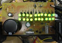
I powered up one channel with a dummy fet in place of Q13, with its drain pulled up to the +30V supply in order to check out the biasing of Q2 and jfets Q3-Q12. Bias current on Q2 is as planned (~3ma), and Q3-Q12 are all pretty closely matched at around 10ma apiece. As an added bonus, the voltage across the source resistors is such that they could easily be replaced by a pair of GaP green LEDs. I may do this with one channel and compare the two.
Here's a Beast board populated with the LED biasing option. The bias current in each output jfet is a little high, and as can be expected, consistency of bias current from fet to fet is worse, as there's only ~30 ohms of incremental impedance for the string of two LEDs, as opposed to the 430 ohms used in the RC biasing scheme. Adding some ballast resistance in series with each LED string would help consistency, at the expense of reducing open loop gain. Adding a negative supply to the drain of the P-channel csource follower and its gate resistor would allow dialing in the output jfet bias more precisely, at the cost of a few more parts. Betcha the LED bias sounds tighter than the RC bias, though.
Attachments
I know there haven't been any comments yet, so it might seem kinda lonely out there...
People, myself included, are watching this with great interest!
BTW, what is the purpose of Q13? I'm still very new to all this...
People, myself included, are watching this with great interest!
BTW, what is the purpose of Q13? I'm still very new to all this...
The J110 (Q3-12) is rated for only 25V VDS, so you can hardly expect it to hold off 300 V. It's only good for ~150 mW realistic power dissipation, so you can hardly expect it to stand up to (300V X 0.1A)/10. So, Q13 is the top half of a cascode, biased by current source Q17 and resistor R37. It pins the drain voltage of Q3-Q12 at ~15V (actual VDS ~10V). This keeps all those little fets from blowing up due to overvoltage or overpower. Q13 is rated for 800V VDS, and is a solid TO-247 device that can handle 30W dissipation with an adequate heat sink. You want a high voltage rating for Q13, as its drain can swing considerably above the +320V rail when the amp is driven hard, expecially if the load is accidentaly removed. I also have a fair number of the 800V fets around (a cheap Electronic Goldmine buy), so I have no qualms about using them
The board is laid out so I could alternatively use a single Lovotech jfet in place of all those J110s, but I'm saving that mischief untill later (much later).
This project came out of the initial discussion in the "Beast of a Thousand JFETs" thread, where I mentioned that I had a little project going with a few J110s in parallel cascoded by a HV mosfet. That particular board was a bit wimpy (only 3 fets), so I decided instead to gin up something that could command a little more respect in the living room. If done right, this amp should be good for somewhere in the vicinity of 10-15W/channel.
Ok, good! I thought it was a cascode... 🙂
So is the point of the HV to use the output transformer? Or just because?
Regardless, it's very interesting... 😀
So is the point of the HV to use the output transformer? Or just because?
Regardless, it's very interesting... 😀
I use the output transformer and HV as an effective way of putting 100ma to work. It also causes anguish to the easily offended.... This amp is in good company, as I have two other solid state designs that use high voltage and output XFMRS. Check out the "Sic Puppy" and "Das Ist Aber Schade" threads for examples.
A more extreme implementation of this project could be ginned up using a lot more jfets and a lightbulb/resistor/current source load, a more solid-state type supply voltage, and capacitive coupling to the load, but my hair has enough grey in it as it is without trying to match up yet more jfets (look what it did to NP). Besides, JFETs in TO-92 package are getting to be a very scarce commodity, and I dislike tying up too much of my precious stock just to prove some bizarre point.
Imagine this amp as a solid-state version of a 2-stage partial feedback SE amp, with pentodes for both input and output duty. Having said that, power pentodes with 50-100 mS of transconductance are rather thin on the ground. A beam triode like the 6HV5A comes close, but those tubes require scary plate voltages to make them wake up.
Distinguished silver - right- I've heard that one before. I guess grey/silver locks are a badge of honor for those who have spent years attempting to unscrew the inscrutable...Dealing with customer types that want three or six or so impossible things before breakfast (for no money) will also bleach out the locks, if you haven't ripped them out already in frustration.
I'll be slogging on with the basic RC bias version of the amp for the initial implementation, as it "just works", and I don't have to do any extra tweaking to get a working first-pass amp. Those who decry expedience can scoop me by building and debugging an LED-biased version of the amp. Any volunteers? I thought not.


- Status
- Not open for further replies.
- Home
- Amplifiers
- Pass Labs
- The Beast with a Dozen Jfets