byteboy,
the efficiency at maximum power is always the same. Depending on voltage and bias the load that gives maximum power will differ.
Two very nice formulas that will give you all the results you want :
1. V = I x R
2. P = V x I
you can use both of them and make a nice spreadsheet😀
When you are ready doing this you will understand the way things are working in an Aleph, Aleph-X or any other amp.
william
Spreadcheats
I hope you were not offended by my previous post, wuffwaff, and that you know what I meant by "no spreadcheats please".
For the sake of you not getting my point, I meant that by using a spreadsheet, the ways the formula's (as mentioned by you) are used/combined, are more or less "hidden" and the calculations are not always transparent to the average DIYer and thus cannot be easily judged for their correctness.
See the spreadsheets with differing results from the one you made...........🙄
In general I distrust spreadsheets, unless the ways the formula's are used are obviuosly clear and/or documented.
Actually I did try to make a spreadsheet, but it's still a spreadcheat because the ways I tried to use the formula's seem to be wrong..............😀
Hello Byteboy,
no, not offended. I just meant to say that the best way to understand the different factors that have an influence is to try and make a spreadsheet.🙂
william
no, not offended. I just meant to say that the best way to understand the different factors that have an influence is to try and make a spreadsheet.🙂
william
There actually is an Aelph X spreadsheet floating around this forum somewhere. I wish I could remember where it is!
Anthony
Anthony
Netlist said:
I would really like to se fig1 in that WIKI.......🙄
Is it the schematic used in the newest groop order for PCB's?
Anders
The link to Figure1 is now in the WIKI.
The figure is in .zip format, and decompressed it is a quite huge .jpg. If suitable to Grey, it could be resized a bit for a 800 X 600 view.
/Hugo
The figure is in .zip format, and decompressed it is a quite huge .jpg. If suitable to Grey, it could be resized a bit for a 800 X 600 view.
/Hugo
Perhaps I should start planning the gala event that will
accompany this thread lurching to 500,000 views.
accompany this thread lurching to 500,000 views.


i'm populating my Aleph-X board, and to get .22 ohm resistors i
was going to parallel the Panasonic 0.47 ohm 3watt at 5%
resistors. But when checking their actual value - they're more like
1 ohm resistors. I would have to parallel way to many of them to
get to .22 ohm. I guess being 5% tolerance pieces they don't
follow the formula for paralleling resistors - becuase even at 5
in parallel i was only down to .5 ohm. I'm just going to spring for
the Mills resistors, but was just wondering if anyone else had
noticed this.
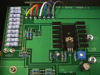
then i was looking at this picture from the XA-200 and wondered
what these resistors were for.
was going to parallel the Panasonic 0.47 ohm 3watt at 5%
resistors. But when checking their actual value - they're more like
1 ohm resistors. I would have to parallel way to many of them to
get to .22 ohm. I guess being 5% tolerance pieces they don't
follow the formula for paralleling resistors - becuase even at 5
in parallel i was only down to .5 ohm. I'm just going to spring for
the Mills resistors, but was just wondering if anyone else had
noticed this.
then i was looking at this picture from the XA-200 and wondered
what these resistors were for.
Attachments
moe29 said:i'm populating my Aleph-X board, and to get .22 ohm resistors i
was going to parallel the Panasonic 0.47 ohm 3watt at 5%
resistors. But when checking their actual value - they're more like
1 ohm resistors. I would have to parallel way to many of them to
get to .22 ohm. I guess being 5% tolerance pieces they don't
follow the formula for paralleling resistors - becuase even at 5
in parallel i was only down to .5 ohm. I'm just going to spring for
the Mills resistors, but was just wondering if anyone else had
noticed this.
then i was looking at this picture from the XA-200 and wondered
what these resistors were for.
Clear indication of measurement error wouldn't you say? If one is 1 Ohm and 5 in parallell is 0.5?
The XA-200 resistors look like the output resistors.
Those are one of two banks of output resistors, arrayed to
as to have both halves interleaved, so you are seeing two
banks there, each 1/2 of the total.
as to have both halves interleaved, so you are seeing two
banks there, each 1/2 of the total.
Originally posted by moe29
i'm populating my Aleph-X board, and to get .22 ohm resistors i was going to parallel the Panasonic 0.47 ohm 3watt at 5%
resistors. But when checking their actual value - they're more like
1 ohm resistors. I would have to parallel way to many of them to
get to .22 ohm. I guess being 5% tolerance pieces they don't
follow the formula for paralleling resistors - becuase even at 5
in parallel i was only down to .5 ohm. I'm just going to spring for
the Mills resistors, but was just wondering if anyone else had
noticed this.
Hi moe,
when You have measured this with an ordinary DVM this is quite normal as those are not very precise in the lowest ohm range (typically 200 Ohms). Moreover with a 2-wire measurement You`ve had the value of the resistance of Your measurement leads included in the result. For accurately measure low value resistance You should use a 4-wire (kelvin) measurement configuration.
Hello every body, that my first post on Diyaudio. I follow with interest all whats around the Aleph X Project since the past month. Since there is a new group order of AX pcb and friend of mine and me decided to plan the building of Aleph X mono-blocs.
After few thinkings about, we fixed the project around 50W power mono blocs. Our Speakers have about 98-100bd sensibility. but after reading some answers from Neslon Pass about the minium rail voltage to be nice with Ax we look to go with about 70W Blocs (19-20 rail V with 6-7A bias)
For this blocs, because of less place i can't use bigger Heatsink than 2 of these
Heatsink per bloc. They allow me a K/W rate of 0.125 per chanel. I cant go lower (about 0.1 K/W) by adding on more half smaller in the front of the Bloc.
In first instance due the low power wanted we planed to use IRF 044.
The power supply will be assumating through one Toroidal transformer (800Va) and filtrate by une CRCRCR circuit build with 6 Caps BC C154 47000µF/40V and 4 res. (100-300mR/25W) per bloc
The think we don't be abble to fix and here is my question is the voltage of the transformer needed, to have 19-20V on rail after crcrc. Psud gives (may be we make mistakes in parameters of Psud) us around 19V rail with 15 V secondary transformer. It seems me strange since we have normaly a lost of 1-2V after rectifying bridge, and 3-5V more lost after filtering.
Am i Wrong or Not? In the case i have rigth with my estimation of V lost through rectifying bridge and crcrc i will need a 2x18V toroidal : 18*1.414=25.45V - 2V (lost in rectifying bridge) -5 (lost in CRCRC) give me 18.45V rail that can be used by the AX main board.
Thank for you answers and forgive me for me bad english.
Marc
Marc,
normally psud gives you the right answer if you give it the right data. 2V over the bridge is a bit too much, more like 0,7-0,9 volts. What output impedance did you choose for the transformer?
william
normally psud gives you the right answer if you give it the right data. 2V over the bridge is a bit too much, more like 0,7-0,9 volts. What output impedance did you choose for the transformer?
william
As we can see in the picture at http://www.diyaudio.com/forums/showthread.php?postid=59134#post59134 there is a electrolytic capacitor in the current source of the differential pair. I think, that more capacity then 0.1 uF like in the standard Grey’s version is due to increase of PSSR. How big this capacitor could be without problems at switch on the amplifier?
wuffwaff said:Marc,
normally psud gives you the right answer if you give it the right data. 2V over the bridge is a bit too much, more like 0,7-0,9 volts. What output impedance did you choose for the transformer?
william
Thanks for the reply,
The transformer inpedance output his automatically calaculated when i give to PSUD the V amount and the A amount from the transformer.
Marc
My experience with the blue Panasonic resistors has been that they're pretty accurate. I'd suspect the meter.
Unless you just like hammering yourself over the head with trivia, I wouldn't sweat +-.5 volts on the rails. The difference in power output, heat dissipation, etc. will not be worth worrying about. The circuit itself isn't going to come unglued over half a volt. Or even a volt.
Grey
Unless you just like hammering yourself over the head with trivia, I wouldn't sweat +-.5 volts on the rails. The difference in power output, heat dissipation, etc. will not be worth worrying about. The circuit itself isn't going to come unglued over half a volt. Or even a volt.
Grey
Right, sometimes you just have to tell yourself to just build it and see! 🙂
then go from there... i will forge on with my test channel
then go from there... i will forge on with my test channel
- Home
- Amplifiers
- Pass Labs
- The Aleph-X