After a sojourn near the Sheetrock Cliffs, the stranger came back to DIYtown to quench his thirst and get supplies. That evening, he dropped by the Pass Saloon for a drink.
The corner table was empty and the stranger sat there alone, watching the other people in the bar. Not far away, several young men were holding strips of paper, regarding them closely. Twisting them. Folding them. They were trying to do something, but it was not immediately apparent what.
After they'd been at it for a bit, a man seated at another table got up and stomped unsteadily to their table. "It can't be done! Can't be done, I tell you! It's unnatural. There's no way it will work. Trust me. I know about these things."
The EE Kid. Again.
The stranger watched for a bit longer, then it came to him what they were trying to accomplish with their strips of paper...
Let's follow this through the circuit and see what happens. To begin with, let's assume a perfect, ideal front end; maybe a 2SK389. Then let's couple this to real world MOSFETs, one with Vgs=3.9V, the other with Vgs=4.0V, just as an example.
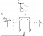
Start with, say, 4V DC across each of the load resistors (R23 & R25 on the original schematic back on page 1). The DC offset across R25 serves as the bias at the Gate of Q2, one of the output MOSFETs. Since it's 4V, and lets make this the 3.9V MOSFET, Q2 turns on and begins to conduct. In fact, it conducts a little hard and the -OUT goes a little negative. The feedback loop coming back through R16 carries a fraction of this signal back to Q5, which is the other side of the input differential. Since the voltage is negative, Q5 inverts this and the result is that the output goes a little more positive across R23.
The voltage across R23 is the drive for Q11, the output MOSFET on the other side. Since it was perfectly balanced already at 4V, both DC offset and Vgs, it now begins to conduct a little harder, driving the +OUT more negative. This, in turn, goes back through R30 to Q7, which drives that output positive and causes Q2 to conduct harder.
<i>Voila!</i>
A relative DC offset has become an absolute DC offset.
So is the circuit unstable? After all, that sounds an awful lot like positive feedback.
When the circuit is properly built and adjusted, it is stable. It won't go running away from you. There are enough functioning units in the field now that you don't have to take my word for it any more. However, there have been posts that people had odd results with what they thought were well-matched front end devices. Now you can see why.
The front end devices are not only matched against each other, but against the outputs' Vgs. A slight mismatch in outputs can lead to a perfect front end being a burden rather than a blessing.
This is why it's worthwhile to take a little extra care in matching the outputs across the amp, i.e. Q2 matched to Q11. The more nearly equal they are, the closer you can match your front end.
Ain't science wonderful?
Will someone please call IRF and have them start making a dual IRFP044...
The stranger tore a short strip of paper from the bottom of a Wanted poster tacked to the wall at his shoulder and waited. After a bit, the EE Kid's words of discouragement had the effect he'd intended and one of the greenhorns decided to quit, thinking the task impossible. He rose from his seat, cast his gaze around the room one last time...and stopped, his eyes locked to those of the stranger.
Quite deliberately, the stranger held up his strip of paper and brought the ends together, forming a loop. Then he twisted one end, one time, forming a Mobius Strip.
The greenhorn stared, then the implication hit him and he began to laugh, silently at first, then out loud. Grinning, he sat back down and picked up his piece of paper again, reproducing the Mobius. He delightedly traced the surface as it became the inside, then the outside again. By then, the other young men at the table were twisting the ends of their strips of paper, forming their own Mobius Strips. The first one held up his strip so that the EE Kid could see, then twisted one end again.
The expression on the Kid's face turned sour. He turned and gave the stranger a baleful glare.
The stranger stood, tipped his hat to the pretty brunette behind the bar, and walked into the night.
Grey
P.S.: Mike, the DC offset will change as the amp warms up. No problem. Just be sure to adjust the circuit when it's hot and it will be good to go. The next time you turn it on, it will do various gyrations, but will settle back in when it gets back to its normal operating temperature.
The corner table was empty and the stranger sat there alone, watching the other people in the bar. Not far away, several young men were holding strips of paper, regarding them closely. Twisting them. Folding them. They were trying to do something, but it was not immediately apparent what.
After they'd been at it for a bit, a man seated at another table got up and stomped unsteadily to their table. "It can't be done! Can't be done, I tell you! It's unnatural. There's no way it will work. Trust me. I know about these things."
The EE Kid. Again.
The stranger watched for a bit longer, then it came to him what they were trying to accomplish with their strips of paper...
Let's follow this through the circuit and see what happens. To begin with, let's assume a perfect, ideal front end; maybe a 2SK389. Then let's couple this to real world MOSFETs, one with Vgs=3.9V, the other with Vgs=4.0V, just as an example.
Start with, say, 4V DC across each of the load resistors (R23 & R25 on the original schematic back on page 1). The DC offset across R25 serves as the bias at the Gate of Q2, one of the output MOSFETs. Since it's 4V, and lets make this the 3.9V MOSFET, Q2 turns on and begins to conduct. In fact, it conducts a little hard and the -OUT goes a little negative. The feedback loop coming back through R16 carries a fraction of this signal back to Q5, which is the other side of the input differential. Since the voltage is negative, Q5 inverts this and the result is that the output goes a little more positive across R23.
The voltage across R23 is the drive for Q11, the output MOSFET on the other side. Since it was perfectly balanced already at 4V, both DC offset and Vgs, it now begins to conduct a little harder, driving the +OUT more negative. This, in turn, goes back through R30 to Q7, which drives that output positive and causes Q2 to conduct harder.
<i>Voila!</i>
A relative DC offset has become an absolute DC offset.
So is the circuit unstable? After all, that sounds an awful lot like positive feedback.
When the circuit is properly built and adjusted, it is stable. It won't go running away from you. There are enough functioning units in the field now that you don't have to take my word for it any more. However, there have been posts that people had odd results with what they thought were well-matched front end devices. Now you can see why.
The front end devices are not only matched against each other, but against the outputs' Vgs. A slight mismatch in outputs can lead to a perfect front end being a burden rather than a blessing.
This is why it's worthwhile to take a little extra care in matching the outputs across the amp, i.e. Q2 matched to Q11. The more nearly equal they are, the closer you can match your front end.
Ain't science wonderful?
Will someone please call IRF and have them start making a dual IRFP044...
The stranger tore a short strip of paper from the bottom of a Wanted poster tacked to the wall at his shoulder and waited. After a bit, the EE Kid's words of discouragement had the effect he'd intended and one of the greenhorns decided to quit, thinking the task impossible. He rose from his seat, cast his gaze around the room one last time...and stopped, his eyes locked to those of the stranger.
Quite deliberately, the stranger held up his strip of paper and brought the ends together, forming a loop. Then he twisted one end, one time, forming a Mobius Strip.
The greenhorn stared, then the implication hit him and he began to laugh, silently at first, then out loud. Grinning, he sat back down and picked up his piece of paper again, reproducing the Mobius. He delightedly traced the surface as it became the inside, then the outside again. By then, the other young men at the table were twisting the ends of their strips of paper, forming their own Mobius Strips. The first one held up his strip so that the EE Kid could see, then twisted one end again.
The expression on the Kid's face turned sour. He turned and gave the stranger a baleful glare.
The stranger stood, tipped his hat to the pretty brunette behind the bar, and walked into the night.
Grey
P.S.: Mike, the DC offset will change as the amp warms up. No problem. Just be sure to adjust the circuit when it's hot and it will be good to go. The next time you turn it on, it will do various gyrations, but will settle back in when it gets back to its normal operating temperature.
fun story, Grey
excellent wit....
Hey Grey, you mentioned that the gain could be adjusted by changing the values of R23 and R25. Would you mind explaining what a lower value resistance does vs. a higher value? I don't want to hurt my AX by screwing around without some guidance.
Thanks,
John
excellent wit....
Hey Grey, you mentioned that the gain could be adjusted by changing the values of R23 and R25. Would you mind explaining what a lower value resistance does vs. a higher value? I don't want to hurt my AX by screwing around without some guidance.
Thanks,
John
Grey, I really enjoy reading your posts. I am glad you came back. I do need to do a better job matching. I am running 4 MOSFETs now instead of 8. I am using IRFP260n's and only half as many. The problem is not as bad. I need to get bigger heatsinks. They are on the way. How about a group buy for a 5 channel mini-A?
Mike,
I'm still trying to find ways to use up all those blasted IRF644s I bought that wouldn't match nicely. I think what I need to do is take a page from Nelson's book and buy some really efficient 8 ohm tweeters, then build a couple of smallish Aleph-Xs to biamp with. For the woofer, I could...wait a minute, I'm getting distracted, here. Will someone fetch a lasso and snag my imagination before it gets over the horizon?
John,
Your question kinda branches out in several directions.
Let's take the resistors, <i>per se</i>. Imagine a gain device--doesn't matter what kind, for this they're all the same--and put a signal into the grid/gate/base. This signal will control the current that flows through the device in much the same manner that a sluice gate determines how much water a farmer uses to irrigate a field.
Now, for an extreme example, let's say that there's no load resistor (i.e. R23 & R25 removed entirely from the circuit) at all. Effectively, we have a zero ohm resistor, right? In this case, all the current that you've just controlled runs straight back into the rail without doing any useful work. No signal. Bummer.
Okay, so we put a resistor into the circuit. Don't worry about the value for the moment...it's just a resistor. When the varying current we've just created hits that resistor, it creates a varying voltage, i.e. a signal.
Now, we're getting somewhere.
So, Grey, if putting a resistor in there is such a great idea, why not put in an infinite resistor and get infinite signal?
If only it were that simple.
An infinite resistor is an open circuit. No current will flow at all. The gain device would switch off and we'd be back to no signal. Bummer.
So what we need is an in-between value.
Here we start looking at the output MOSFETs for hints as to what to do. Since the MOSFET wants to see something like 4V in order to do its job, and since we've already got a bias current in mind, we're going to go with something around 400 ohms. Well, okay, so there's not a 400 ohm resistor in the catalog...we can go with 392 ohms. Close enough for government work.
Waitaminnit! Whuzzat bias current thingy?
Whenever possible, you'd prefer not to go turning a gain device off and on. It complicates things. It takes time to rev up. So you leave it running all the time if you can--class A. The front end differential in the Aleph-X runs in class A (as do nearly all low level circuits). I mean, might as well, it only draws a watt or two. We're not talking some beastly output stage here.
Since the inputs are on all the time, there's a steady current flowing through the gain devices even when there's no signal. They're warmed up, ready to go.
So we've got this small DC current keeping the front end toasty and warm. Why not let it do double duty and keep the outputs biased, too?
Nothing like killing two birds with one stone, eh?
Now, you could decouple the front end from the outputs with capacitors and let the DC across the load resistors be any old random value. But then you'd have to provide a separate DC bias value at the Gate of the outputs, and that's so inelegant.
So the trick is to play your bias current against the load resistor value to come up with something around four volts. It's not as limiting as it seems. You can drop in JFETs if you want to decrease your gain (they don't have as much transconductance as MOSFETs), or put in bipolar transistors if you want more gain (watch out! easy to get too much gain).
If you want to play with front ends, I'd recommend building a simple differential on your kitchen table and fiddling with it until you get something you like in terms of gain, but still with that 4V offset. Then you can pretty much just patch it in.
For reference purposes, the stock front end has about 20dB of gain and the amp as a whole has about 20dB of gain. If you add 5dB to the front end, the entire amp will have 25dB of gain. If you subtract 5dB from the front end, the whole amp will end up with about 15dB of gain.
Or, for something completely different, you could change the feedback ratio...
Oi!
My fingers are tired. Lemme rest my knuckles a minute and get a few things done (I'm at work). If you want to tackle the feedback route, say so, and we'll take another whack at it.
Grey
ok, if i use high efficiency speakers. Lets say 100 dB/W or so. Wouldn´t it be the best way to use a jfet input stage for i) less noise ii) lower gain ?
Sounds like a good plan to me.
Oh, one other thing. I said 2SK389 above. That's the N one. I should have said 2SJ109--whichever is the P one. I must have a mental block against the 109. Don't know why.
Grey
Oh, one other thing. I said 2SK389 above. That's the N one. I should have said 2SJ109--whichever is the P one. I must have a mental block against the 109. Don't know why.
Grey
i was just wondering about the gain devices we use in audio
circuits. They aren't designed for audio purposes are they...
in other words they're not tailored to fit audio needs are they.
Does this impose limitations on fidelity? Would we have better
sounding circuits if, for example like Grey mentioned, we had a
dual IRFP044... or MOSFETS that had "audio tendencys" desinged
in to them.
or am i just way off the road? Gain devices are basic building
blocks and it's how you use them that matters.
sorry if i'm way off topic... it's just most of what's discussed goes
over my head... i'm trying to learn and questions pop in to my
head 🙂
btw, thanks for the informative and amusing text Grey!
moe29
-----------------------------------------
a man's got to know his limitations
------------------------------------------
There are some. Motorola has a fair selection of bipolar power transistors that specifically say audio in big, bold letters on the spec sheets. There are others, too. However, we're usually faced with using "low noise" or "general purpose" devices.
If it's any consolation, the same thing's true for tube guys. The 6550 was designed to be the big boy on the block for audio output tubes, but a lot of the other tubes being used in audio were designed for odd things like horizontal deflection in TVs. The 6AS7/6080 power triode was designed to be used as a series pass element in voltage regulators. It didn't take long for it to make its way into the first OTL circuits, though, and it's been a mainstay ever since.
Whatever works. We're a niche market as far as the parts folks are concerned. Generally speaking, not worth the trouble to design for.
Grey
beyond cool.....
Thanks for the detailed and interesting tutorial, Grey.
Despite the excellent examples, I'm not sure I understand how the 400 ohm resistor value was calculated in order to deliver 4 volts across the FET. If you have a second, it's a lesson I'd enjoy reading.
It sounds like the 400 ohm resistors should remain in place to keep the necessary 4 volts that the existing circuit requires. So, the second idea of replacing the 9610s with 2SJ109s seems to be the solution. I have 110 db horns and I'd trade less gain for more finesse. I don't know how to calculate the correct value for the surrounding circuitry. Is there a chance you could perform this task? Or, even better, teach us how to model this for ourselves? Another thing, do I use the existing 9610 current source, or does this need to be a 2SJ109 as well?
Many thanks, Grey
John
400 ohm resistors are calculated from Ohms Law. For a given current it's easy to calculate the resistors value to get 4V drop. R = U/I where current is about 10 mA if I remember correctly.
Now, the question is, is the sound improves when increasing the current through differential pair? I'm running them slightly higher by using 300 ohns resistors, but didn't perform any comparisons.
Now, the question is, is the sound improves when increasing the current through differential pair? I'm running them slightly higher by using 300 ohns resistors, but didn't perform any comparisons.
Thanks Peter,
How was 10 mA decided upon? Is this a specification from the FET's data sheet?
I assume (please correct me if I'm wrong) Ohm's law say's to divide 4 volts by 0.01amps. This gives me 400, the value of the resistor. What confuses me is how this formula interacts with the rail voltages: With different rail voltages wouldn't the 400 ohm resistor will pass different amounts of voltage and current?
John
400 ohms
Assuming that one is trying to get 4 volts for the bias of the second gain stage, 400 ohms gives about the best gain for the 9610 mosfet diff pair front end. A larger resistor value for the same 4 volts DC will give require less current through the front end. This will give less transconductance for the 9610 mosfets as less bias current will be needed to get the same 4 volts DC required for the second stage bias. The gain for each side is one half the transconductance of each 9610 times the 400 ohms. The transconductance is proportional the bais current but it is not a linear relationship due to the device characteristics of a mosfet biased in this region. I am afraid we are getting beyond ohms law at this point.
Lowering the resistor value lowers the gain since the resistor value starts to decrease faster than the transconductance increase with increasing bais current. Seems I remember the gain of the front end being highest for around 400 ohms given the goal of having 4 volts across this resistor when I was tweaking this with Spice modeling. One would think that Mr. Pass sought the max gain from the front end to arrive at this value but perhaps other factors were also considered in addition to this. Mr.Pass?
The DC voltage across the 400 is determined by the current source for the front end and is independent of the rail voltage for a given current source value.
Earl
about GRollins's "infinite resistors"
Of course you can use current sources instead "infinite resistors". They will ensure current flow and will have almost "infinitive" impedance for audio signal. So you'll have excellent gain and current regulation.
These current sources must be calculated for half current than drain current source for input transistors.
Here is something I was playing around with...
keep in mind that I'm fairly new at all this too. It's just to present the concept. It actually simulated well. I was using 4.75K output to current source "balance" resistors, and 100K feedback resistors. Sensitivity was about +/- 1 volt for full output.
Let the nitpicking/flaming begin!
keep in mind that I'm fairly new at all this too. It's just to present the concept. It actually simulated well. I was using 4.75K output to current source "balance" resistors, and 100K feedback resistors. Sensitivity was about +/- 1 volt for full output.
Let the nitpicking/flaming begin!
Attachments
John,
you actually want to try to get more than 4 volts, 5 is probably a good number, so that the Vgs on the Mosfet, after you burn .5 volts on the source resistors, is at around 4.3V.
You basically want to be damn sure the gain mosfets are in full conduction, being .3-.4 volts above their Vgs.
Try to find some mosfets for the diff pair that are on the low end of Vgs say ~3.6V
OR play with the load resistor a bit to get to that point. That is just another way to say what Grey was saying about matching the input diff to the output.
That has been the biggest source of problems for me. The famous 60mV DC offset I was having at the speaker is GONE. I did the first board ultra carefully and I was getting 60mV DC and weird source resistor voltage drops, I slapped the second board together using input diff mosfets with 3.6 Vgs and everything worked perfectly right off the bat. The mosfets were matched pretty carefully but not -super- carefully. Now it starts at 18mV and goes to 0 in ~5 min.
I tried to use a matched pair for the current sources and a different pair for the gain matched at a lower Vgs and that works too. Vgs difference between the CSs and the gain mosfets can be nulled out pretty effectively. That cuts down on the number of mosfet one needs to buy.
What happens if the voltage drop on 400ohms resistors is at the higher end, let's say 5V? Does it make any difference?
Peter, IMO 5v is what you really want. Right now I have 4.8V, 5V should be even better. Basically you don't want the current flow to be regulated by all 4 output devices. The gain should be in full conduction while the CS does the job of controlling how much current is flowing.
I guess when the CS and gain are "fighting' for who's controlling the current weird **** happens. I suspect the 4.7k to the source of the input diff play some role too.
I guess when the CS and gain are "fighting' for who's controlling the current weird **** happens. I suspect the 4.7k to the source of the input diff play some role too.
I also settled for higher value of 4.8V. From previous posts it seems like the current flowing through the differential pair has influence on the gain. I didn't realised that. I'm using 300 ohm drain resistors (4.8V drop) and my feedback resistor is 220K while input to ground resistor is 33k. The gain is around 26dB.
- Home
- Amplifiers
- Pass Labs
- The Aleph-X