If 500k hits is the goal, I have an easy solution...add the Aleph-X Builder's thread to this one.
If you want 1M, tag in the other related threads for high power versions, etc. It might not be there, but it should get within spitting distance.
Me? I'm working on power JFET ideas. Progress has been made. Some ideas haven't panned out, but others have. I'll be plugging away at this as time becomes available.
Grey
GRollins said:It's possible to do this, but I think that you'll find that it's more trouble than it's worth. You're going to drastically change all the operating parameters when you change the rail voltage. The DC offset will have to be resettled each and every time you do this...might be best to go for a DC servo to reduce the fiddle factor.
It goes without saying that you will not want to change the rail voltage with the amp running.
Grey
Yes, I guessed it wouldn't be all that simple, and of course the idea wasn't to do it 'on the fly', but since there have been a couple of hundred posts about what voltage and bias to choose, including some excellent spreadsheets, I was hoping it wouldn't be too hard to switch between two. I'd of course like to avoid servos. Both You, Mr Rollins, and Mr Pass seem to agree on that if you cant do it with a couple of resistors, it's not worth bothering.
Apart from the fiddling with DC offset, couldn't one, like I guess William was talking about, have a mulipole switch/relay that runs two trannie secondaries in parallell or in series... or, I don't know...
Anything that means I don't have to resolder the whole thing to change voltage and bias...
Of course just the bias itself can be fiddled with, but my idea was to keep the same dissipation for the FETs and go for either high voltage, for 8 ohm load, or high current, for 4 ohm load.
I I thought to myself every time I was cramming the night before a physics exam: Why can't things just be simple?
/hilbert
PS. By the way, Mr Rollins, is there any way for us up here in the north [N 57°41,5′, E 11°56,6′] to get hold of any of the stories you make a living of?
analogair said:Where do you guys see the hits / counts ?
It's on the top page of the forum - the number of views is
listed for each thread.
[F5] [F5] [F5] [F5] [F5] [F5]

GRollins said:The DC offset will have to be resettled each and every time you do this...might be best to go for a DC servo to reduce the fiddle factor.
Grey
I don't know all that much about theese things, so please be gentle. I'm not giving up just yet. Here goes:
Since wire and resistors are relatively cheap whereas FETs and xformers are not, could one in any way have two separate rail pairs, one pair driven for 4 ohm, the other for 8 ohm?
If that would be possible then powering down, switching rail, and powering up, shouldn't, once it's tuned, crave more DC fiddling than just powering up and down a 'normal' AX, should it 😕
/hilbert
PS (again). Gothenburg [N 57°41,5'] is almost at the same latitude as Fort Nelson in Brittish Columbia [N 58° 50']. What's in Fort Nelson? A Zen monastery? The Federal Current Reserve [a 1 Gf cap]? Ok, sorry, It's soon midnight here. I'm off to bed.
I'm not sure that I'm following what you're saying, but it sounds as though it would be easier just to build two amps and swap inputs/outputs.
I'm not trying to discourage you from building your dream amp, but I think you'll find that the fiddle-factor will be much higher than you anticipate. If you like fiddling (I used to, but now am more of a mind to set it once and go on to the next thing), then this could well be the ultimate project.
Sit back and think about the 'why' of this. Are you seeking a technical exercise in the sense of a proof-of-concept piece? Are you looking for an amp to play with on a day-to-day basis? Are you wanting two amps for the price of one? If you clarify your goal, then your path will become obvious. You can then follow it more easily.
Grey
GRollins said:I'm not sure that I'm following what you're saying, but it sounds as though it would be easier just to build two amps and swap inputs/outputs.
Yes, no doubt, but what I meant was that I'd like to keep costs down by only using one xformer and one set of FETs.
Yes, maybe that is what I want...Are you wanting two amps for the price of one?
I do enjoy fiddling a bit, but not THAT much...If you like fiddling (I used to, but now am more of a mind to set it once and go on to the next thing), then this could well be the ultimate project.
Sit back and think about the 'why' of this. Are you seeking a technical exercise in the sense of a proof-of-concept piece? Are you looking for an amp to play with on a day-to-day basis? Are you wanting two amps for the price of one? If you clarify your goal, then your path will become obvious. You can then follow it more easily.
Grey
"If you don't know where you're going, It doesn't matter wich way you go"
When I started thinking about it it was both as a proof-of-concept and a way of building an amp that can drive any load without costing an arm and a leg and that you could listen to without having to sit under a cold shower while doing so.
I guess it is futile.
I'll have to buy a massive xformer, MASSIVE heatsinks and a lot of FETs and build one with both high voltage and bias. Perhaps I should design a combination of an AX stereo pair and an espresso machine. When the amp has settled it's time to draw a double shot of sweet, rich, choclaty espresso to go along with the sweet, rich, crisp sound. I think I might contact Isomac or La Pavoni about that...
One thing I've been wondering (and maybe it's in the thread and I just didn't get it) and that's the thing about biasing. I believe Mr Pass said that key is total bias, nut bias per device. But If one has a lot of devices with a certain total bias, doesn't one run inte the non optimal working range of the FETs when they divide the current up between them?
/hilbert
PS. I wasn't kidding about your stories Mr Rollins, I really would like to read some of them! I'm not sure how to get them here in Sweden, though.
Hi,
if you choose the amount of fets by looking at the dissipation per device and keeping it between 20 and 30 watts you will end up using the fets in the same working range regardless of amplifier size (dissipation wise).
What will change is the ratio between voltage and current.
What do you thinkis the optimal working range for a given fet?
William
The Aleph-X circuit will run pretty warm no matter what you do. Obviously more powerful amps will put out more heat, but human nature being what it is, people tend to buy only as much heatsink as they think they'll need. Okay, okay...sometimes a little less than they need, judging from the number of my-amp-runs-hot posts that you see.
The elegant way to handle this is to do what (I think) wuffwaff is suggesting and adjust the voltage and current by the same ratio. If the voltage goes up by 1.5, then reduce the bias current by 1.5. That way the heat dissipation stays constant and you can use the same heatsinks.
The power transformer will require a little more planning, however. It will have to be able to handle both the high current and the high(er) voltage. That's going to take some time and money.
Power supply caps will be easy: Meet the higher rail voltage requirement.
What modifications the circuit will require will depend on just how wide a range of voltage/current you expect to to use. You're going to need to switch the Source resistors for each of the output MOSFETs if you intend to do drastic current modifications. Perhaps a central driver circuit to power a set of relays that would select the resistors for each MOSFET. If your current changes are more modest, you might be able to get by with changing the resistance in the Aleph CCS.
I still think a servo is the ticket for the DC offset. Changing the operating parameters for the amp is going to knock the DC settings off. That means a trip to the bench to get things tweaked back right again. That will be time consuming. Let the circuit adjust itself. It'll save you lots of time.
Nelson will have to answer your question about what he meant about bias. Speaking for myself, I think in terms of how much current I can get through a single device for linearity. The sum of all the current through all the devices will determine how low an impedance you can reasonably drive.
I don't think my stories make it to Sweden. As far as I know, they're mostly in North America, although a few have made it as far afield as Britain. One of my Victor & Martin stories, Spoiled Rotten, was picked up for an anthology which just came out. Here in the US the title is The Mammoth Book of New Comic Fantasy. In the UK, it's called The Mammoth Book of Comic Fantasy. In either case, Mike Ashley is the editor. (Don't ask me why the American title has 'New' in it. I don't know.) How available those are in mainland Europe, I couldn't say. Amazon has it. Otherwise, try to find the US version of the magazine Analog (snappy title, eh?), as that's where my stuff usually shows up.
Grey
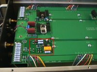
What is the functional of the red erea?
Many thanks Nelson Pass provide the XA200's detail pictures,I look at this again and again and found some special erea,please see attached read area,what's the functional of this erea?cover the unbalance signal to balance signal?
Many thanks Nelson Pass provide the XA200's detail pictures,I look at this again and again and found some special erea,please see attached read area,what's the functional of this erea?cover the unbalance signal to balance signal?
Attachments
Aleph X
Grey, I have tried to digest the Aleph x thread as best I can.
I am building some line array loudspeakers and they will be 96db efficient. I have Aleph 1.2's that I built 6 years ago and the A-75 that I built 12 years ago, but I would like to build the Aleph X.
Has there been actuall updates to your original schematic?
Because of the transformer that I have on hand I can build the rails at about +/- 30volts (these are 2kva transformers). I also have some power supply regulators from some previous projects that I can dust off to reduce the rail voltage and get rid of ripple.
I probably would use a fan cooled heatsink arrangement. I am aware of the dc offset problem from the thread and I think I can get out of that with carefull matching of devices. How many outputs did you actually use? thanks for any help, my eyes are tired from reading over 300 replies. dave
Dave,
Just add Ian's resistors to the front end CCS and you're as current as you need to be. If I were to start over, I'd change a few things, but nothing that really matters.
30V rails will get you somewhere close to 200W. You'll need some beastly heatsinks, but it will also be a nifty amp.
The DC offset thing is pretty tame if you use well-matched devices. People who have persistent DC either didn't match the MOSFETs well enough or didn't adjust the amp properly.
I've built several variants of the Aleph-X, but at the moment I'm more prone to thinking about these power JFETs. I just sent out a batch of parts and have a little clear time this afternoon. Hope to nail down a few final details on that amp. I'll post it as soon as possible.
Grey
Aleph X
Grey, thanks for your kind assistance. When I built the Aleph 1.2's to get rid of some minor power supply hum I used a CLC power supply. I got a suggestion from NP on the air coiled inductor size to use and it cleared up the problem. On this amp I may use a regulator after the Filter Caps feeding smaller caps. I thinking of just dropping enough volts to get rid of the ripple and not have to disappate any more heat through the regualator than absolutely needed. I have also thought about doing what spectral and BAT does and that is locate smaller caps right at the out put devices. My Aleph 1.2's used 24 outputs per mono block.
Did you use a regulator or the standard power supply?
To do this with the Aleph X looks like the same except you would have 6 per CCS and 6 Ouput x 4 for plus/minus rails. The heatsinks of course are the most expensive item especially if you are going to powder coat or chrome plate the Aluminum. I am getting mentally charged up. By the time I finish this NP will have an amp designed that will need to be connected to a Nuclear Power Plant with a direct line. By the way this amp is being mounted on wheels with a "Wagon Style handle" that can be disconnected. I have to use may Lawn tractor to move his designs around. Thanks again, dave
AX A LA Jfet?
Lets try it here, I very well understand that I may be a bit off topic but I thing thats the right place to ask a silly(maybe not) idea that came to my mind some days ago.
Of course as i did not red all the threads since I bought the pcbs(2 years ago or more), somebody else may have though of it before.
So here it is, since I only need less than 10W of power for my horn loaded 15" tannoys, I would like to ask if it is possible to build an aleph-x using extremely low voltage, something like +/-8V lets say. I know this is not possible with IRFP240s as the point falls out of linear region.
BUT what if we try the lovely Lovotech's Jfets that happen to work very linearly in that voltage region?
Regards,
Panos
Panos,
Eight volts will be doable. You'll have to pull way back on the current though and parallel lots of devices to get back up to a useful output.
Another possibility would be to cascode the JFETs, not with MOSFETs, but with JFETs. But if I start throwing out ideas like that, someone's going to think I'm trying to sell JFETs.
(Who, me? Perish the thought!)
There are other ways to arrange things, but the patents in question are still in effect and I am reluctant to add to Nelson's IP troubles. There are enough possibilities out there that we don't need to go that route.
Grey
4 questions about kristijan Aleph-x
after 140 replies I have chickened a bit 🙂 idint find info what I need. my 10 pieces aleph-x pcb reaDY TO GO.. except few things.
I am using Kristijan boards, but slightly modified-thicker traces.
http://www.kk-pcb.com/alephx.html
questions
1. I have excelent vishay dale carbon 1% tolerance 10w resistors. 1ohm. if conect 2 in paralel I get 0.50ohm, this is more, original schematic uses 0,47ohm x4 5w is paralel. can I use 8x 10w 1ohm instead originals.
2. bias Left, right and bias q?what values I should use, can i put resitors there, or pot is needed to achieve some voltage points(like in zen v4) if I put pots from waht position start amp? I am sure I will fire first if set pot to incorect value..
what rssitors is the most critical? I used 1% tolerance 0,6w , but they are not the same. irf 240 and irf9610 are mached at 0,01V
my transformers is 18V secondaries.
also Iwant to use one amp on speakers which has 2 ohm impedanse at 70 and 30hzhz . what modification I shopuld do, to make amp that controls loww region well enought.
note I am speaker designer and not a expert on amps, variac, bias etc .
will wait any input..
😕
Hi Mr. GRollins !!
One question!
I have read some reviews about the Pass Labs XA-160.
Is topology of Aleph X equal to Pass Labs XA-160 ?
And what about the sound between them ?
One question!
I have read some reviews about the Pass Labs XA-160.
Is topology of Aleph X equal to Pass Labs XA-160 ?
And what about the sound between them ?
elviukai,
The Source resistors can be regarded as the "coarse" bias setting. You'll end up with about half a volt across those resistors, so that will tell you roughly what the bias will be. You can use any value you like, but trying to use too high a value (i.e. low bias current) will starve the output stage. You won't like the results. A low resistance value (high bias current) will sound wonderful but you'll need to make sure that you have plenty of heatsinking and a stout power supply.
The right and left pots will not set the amp on fire no matter how they're set...I wouldn't do that to you. They can be used to fine tune the bias and relative DC offset. After that, if you want to pull them out, measure them, and replace them with fixed resistors, feel free to do so. I recommend getting the DC set properly before hooking up a speaker to the amplifier.
I have never gone along with the point of view that there are one or two critical resistors in a circuit and that all the rest are somehow of lesser importance. To my way of thinking, it's all in the circuit path. Note that Nelson disagrees with me on this. His idea of the circuit path is the shortest trace between the input and the output. You can do what you like (and afford) as far as parts quality goes.
A 2 Ohm load is a bit brutal. I would suggest ramping up the bias a little if you're expecting to play very loudly with a speaker that has a wide low impedance area. Again, you'll need lots of heatsinking and a robust power supply.
EDDELARUE,
I have never seen a schematic for the Pass Labs XA amplifiers. I can't tell you how similar or different it might be to any of their commercial product.
Grey
Mr. Grolins THANKS VERY MUCH for EXACT help. I have no problems with heat I can build as large as needed( I already build 500mm x 150mm area heatsinks ,wings height is 100mm , 30 wings) with power supply have 1500VA trafos secondaries 18v. ,I have no problem with capasistance- have plenty of siemens sikorel caps and cheaper nippon chemi pon. I have no problem with diodes-have 70 pieces HFA 25PB60(25A, 27ns,ultrafast,ultrasoft) the best available up to date as far as I know.
I am having only one problem with wilson audio watt/puppy- aleph 3/5 do not have speed,control, and power slam to make puppys realy sing. this is not only subjective performance. I measure spl at higher spl levels. there are big dips at 70-80hz and in lowest octaves. the bigger spl the bigger dips. I am on thoughts to build 2 alepx x( one probably highly biased for pupies) for biamping. as I found reading about comercial aleph xa160 that lowering impedance amp delivers lower power also. only 50w at 2 ohms,and 150w at 8ohm. luckily all region is 4-5ohms anly two impedanse dips are at at 70-80hz 2.5ohm and at 30hz 3ohm.
about biasing higher amp- all I need is to lower those paralel resisitors 0.47ohm(total 0.117ohm) or lowering o.39ohm or something more should be lowered or adjusted. and theese pots 200khom I need to get about half a voltage across )both ends conected to multimeter,or one to ground and other to resitor end?) of each 0,39 ohm resistor? as I understand about aleph x that I can freely experiment with secondaries voltages?
- Home
- Amplifiers
- Pass Labs
- The Aleph-X