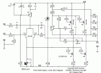
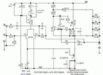
I can find only this one , even if I'm pretty sure that there must be at least one prior
http://www.diyaudio.com/forums/pass-labs/75281-babbelfish-j-pcbs.html
whatever - this is latest schm
NB - source resistors for input LTP are 4R3 , not 43R
http://www.diyaudio.com/forums/pass-labs/75281-babbelfish-j-pcbs.html
whatever - this is latest schm
NB - source resistors for input LTP are 4R3 , not 43R
Attachments
Can someone remind me a few parameters:
- current per device for top half in Aleph J
- current per device for top half in Aleph JX (2 transistor)
- current per device for top half in Aleph JX (3 transistor)
- current per device for top half in Aleph Jango
This is for matching purposes, so voltage / current / temp / whatever parameters would be helpful.
1-1.2A is good. 1.2 is what i believe AJ was biased at. I ran my monoblocks a little hotter. It is really you choice and to be peculiar would mean further investigation of distortion at each bias level. Once you begin to dive into this stuff, you quickly become impressed by the effort needed to find sweet spot.
In addition to modifying R7 to variable 500 to 1k ohms, modifying R27 to variable 40k to 100k or so, and changing source resistors on IRF parts to .22ohms
Would it be beneficial to use .1ohms for the SS100 bias resistors?
Thanks
Bob
Would it be beneficial to use .1ohms for the SS100 bias resistors?
Thanks
Bob
Woudlnt hurt. Would change the DC bias point and also alter amount of gain. I believe it might be necessary to put 10k pot across R8, to adjust currnet through LTP. Adding larger pot in drain of LTP did not help address offset, so i think FE needs more current. Gonna test more today.
what about R125 in place of R100A? any benefits? didn`t manage to find nowhere the datasheet for R125.
I saw that the A in the tail of R100A means they are designed for audio, guess R125 is not
I saw that the A in the tail of R100A means they are designed for audio, guess R125 is not
I must admit I am completely mystified. I hae doing battle with this thing for two days and cannot get the offset below 200mV. This is even using two FQA instead of the SS. I have added pot to ACS, pot across R8, and larger pot to LTP drain, and it just wont close down. I have built 4 successful AJ's for various family members and never had this trouble.
Last thing i tried was adding pot across R8 in LTP CS. While i can adjust it, it does not change the Vdrop across R8, I dont realy understand this. We are talking DC settings here, so any change in the value of R8 should reflect a different Vdrop across that same R8 resistance, because the Vref of the diode does not change.
I am about to take it out back for target practive.
This is too simple. I am missing the forest for the trees.
buzzforb
Is this occurring in both boards? When I did my F4 headphone amp I finally populated another board because I could not get correct settings on the first.
If its one I could sent you my populated boards to experiment with - If its both boards ....
Just shooting in the dark here but what role did the parts we left out play (Q3, R13, R14)????
Best
Bob
Both boards. THe parts left out are just form protective circuit that watches the output.
Its wierd. IT as if the output is setting at an imaginary pooint above ground. I say this because i can take the offset down to its lowest point, turn it a couple more times, it rises slowly at first and then takes off and the offset goes way up. I would think the jfets are bad, but they are really more involved the Ac side of things. I cant see basic DC bias being a problem, even for bogus fets. They are clearly operational.
Its wierd. IT as if the output is setting at an imaginary pooint above ground. I say this because i can take the offset down to its lowest point, turn it a couple more times, it rises slowly at first and then takes off and the offset goes way up. I would think the jfets are bad, but they are really more involved the Ac side of things. I cant see basic DC bias being a problem, even for bogus fets. They are clearly operational.
Last edited:
with schmtc simple as this , I can't really give you more advice than I already did
whatever - role of zener-bjt circ is to have exactly Vzenn-Ube voltage all the time - nature of the beast
what you're changing is current through bjt , not voltage across R8
so R8 voltage is constant
R8 current is variable
ook
gimme R8 value , exact schematic of rest , Ugs for both output Jfet and A CCS mosfet @2A ( or @1A in case you want 2+2 pairs ) and I'll give you recipe for puttin' it live
under condition that you didn't made some systematic mistake for both channels
THats exactly why its irrititating.
R8 is 1k, with pot removed. I can of course lower this with pot if needed.
LTP consist of 2.2K resistor with 10k pot across it. Plenty of Vgs
R27 has 100k pot installed.
Vgs of SS at 2A is about 1.5V. Vgs of FQA at 2A is about 4.2V I have been trying for 1.2A, like original.
One channel has single LTP of j74 with Idss of 10.6
Second channel has dual pair of same rating.
Offset will not come below .250mV even with very well macthed FQA in circuit.
Ook me.
Attachments
what you're changing is current through bjt , not voltage across R8
so R8 voltage is constant
R8 current is variable
Your telling me that no matter what the value of R8, it will always read 8.3V? I guess i can add bjt's to the list of stuff I dont get.
Ref Post # 153
500K Pot should be a 500 Ohm Pot (Make shure the pot is at full resistance)
Or better yet Replace with fixed 220 Ohm + 500 Pot in series (half turn)
I vaguely remember Nelson Pass mentioning this a long time ago.
500K Pot should be a 500 Ohm Pot (Make shure the pot is at full resistance)
Or better yet Replace with fixed 220 Ohm + 500 Pot in series (half turn)
I vaguely remember Nelson Pass mentioning this a long time ago.
THats exactly why its irrititating..........
Ook me.
short both inputs
make as per sch.
later you can rewire it for 2+2 pairs iteration
set upper pot ( input LTP CCS ) to 830R , together with fixed 470R in series (~10mA through LTP) ; or you can put just one fixed 820R instead
set pot in drain of LTP to have approx 390R
power up - set 47K pot in Aleph CCS to read 0V47 across source resistors of mosfet - which means 2A Iq
fiddle with drain pot to have 0 offset
if offset is still in positive - add 220R in series with drain pot , but back it for same value prior to powering up
I know what's problem with your amp - short circ between two headphones , category invented and patented by Might ZM 😉
Attachments
Only thing I havent done is change CCS resistor to 830, still 1k. I still have 2.2k in drain with 10k pot. Gives me more swing than 500R pot and shouldnt hurt anything...if i understand correctly. I only have single RS of .47 and dropping .47V across it. I can adjust the CCS current higher, increasing total bias available, but offset just increases. THe bottom fet is not leveling things off, even with plenty of gate voltage and asking only 1A of it, not 2.
I guess it is possible that chagning ccs to 830 might make huge difference, but didn't work when i had it set to that with parallel pot.
Major short circuit in brain about 8.3 thing. Of course it measures 8.3 no matter what. IT is the R that it is divided by that changes and with it, the current through the CCS. Simply flustered when typing.
Last edited:
buzz - if you tested your Semisouths for Uds@2A , something is very wrong there .
so - pictures , schematic , measurement data in all major points
LTP current isn't thing to fault - you can always compensate with drain resistance setting ;
of course - AC behavior is where it counts , for that current (think OLG)
so - pictures , schematic , measurement data in all major points
LTP current isn't thing to fault - you can always compensate with drain resistance setting ;
of course - AC behavior is where it counts , for that current (think OLG)
- Status
- Not open for further replies.
- Home
- Amplifiers
- Pass Labs
- The Aleph Jango


