Hello,
Don’t you just love it? It takes more time to sort out the test gear and soft ware than the UUT. Is it possible to break this into manageable pieces?
The first one you have done. Loop the sound card from output to input. That was clean.
Next add the voltage divider or the Millett interface card. When that is clean add
the amplifier power supply. No 60 hz, no 120hz, no spray of noise from the diodes good move on add the next thing to the mix.
Bad idea tell me to butt out. I will keep reading. You are ahead of me I will be doing the same.
DT
All just for fun!
Hello,
Don’t you just love it? It takes more time to sort out the test gear and soft ware than the UUT. Is it possible to break this into manageable pieces?
The first one you have done. Loop the sound card from output to input. That was clean.
Next add the voltage divider or the Millett interface card. When that is clean add
the amplifier power supply. No 60 hz, no 120hz, no spray of noise from the diodes good move on add the next thing to the mix.
Bad idea tell me to butt out. I will keep reading. You are ahead of me I will be doing the same.
DT
All just for fun!
You make a very good point. I have been through this countless times.. 😀 Go to test something and find your test setup is seriously broken, spend tons of time fixing test equipment after determining that the test setup was in fact ok. Finally get sorted out, testing DUT takes about 10% of the time spent.. 🙄 Usually it is better the next time around.. The AP is a relative joy compared to lesser devices.. Still dreaming of getting one..
This is how the peer-review journal articles are written. The guy I worked for in college just loved to have articles appear in "Zeitschrift fur Physik" which he felt was the most prestigious for physicists at the time -- and the prep for the experiments was more arduous than the actual experiments. It bored me to tears.
This is how the peer-review journal articles are written. The guy I worked for in college just loved to have articles appear in "Zeitschrift fur Physik" which he felt was the most prestigious for physicists at the time -- and the prep for the experiments was more arduous than the actual experiments. It bored me to tears.
Yeah, but ... you have an AP...
Yes indeed. I'm still trying to get my test equipment together.
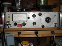
I just fired up a Heath-kit IG-18 my dad gave me. It has probably set 10 years, maybe 20.
At 1Khz, the output was amplitude modulated with all kinds of noise. Finally I got out the manual and went through the cal procedure and it was an instability in the feedback loop that was causing the modulation.
I hooked it up to the HP 333A and got the lowest distortion reading I have seen since I got the DA.
0.029%THD!
So, the HP 333A is good and the IG-18 is good.
Jackinnj, I saw on another thread that you have one of the IG-18s. Have you done the mods in "The Greening of the IG18" by Reginald Williamson?
If so, what did you use for the 40408, 40361 and 40362 transistors? I've found the specs on them, but am not aware of any high gain complimentary pair like that and I don't see them available from Mouser, Digi-Key etc. It looks like the 2N3055/2955 won't cut it.
I did find the 2N5087, and the 40408 does not look special, although I don't have anything on hand that goes above 40V in small signal.
I may put the 6P1P amp back on the bench, drive it with the IG-18, and try to look at it with Audio Tester V3 and the HP333A to see what I get that way.
I'm beginning to think the problem with Audio Tester is mainly with the computer internal sound card and my ground environment. If I can get a good reading with the HP333A and the IG-18, then I may need to get a USB sound solution if I can't get the noise isolated.
Attachments
By the way, there are a couple of IG-18s on ebay at pretty reasonable prices for the quality.
The Williamson mod is here:
Heathkit Schematic Diagram Archive
Here is another mod:
http://www.angelfire.com/electronic/funwithtubes/IG-18_Mod.html
The Williamson mod is here:
Heathkit Schematic Diagram Archive
Here is another mod:
http://www.angelfire.com/electronic/funwithtubes/IG-18_Mod.html
Jackinnj, I saw on another thread that you have one of the IG-18s. Have you done the mods in "The Greening of the IG18" by Reginald Williamson?
If so, what did you use for the 40408, 40361 and 40362 transistors? I've found the specs on them, but am not aware of any high gain complimentary pair like that and I don't see them available from Mouser, Digi-Key etc. It looks like the 2N3055/2955 won't cut it.
Mine is an IG-5218 -- modified, it is capable of 0.02 to 0.03% THD+N%. Those are, I believe, RCA part numbers -- I modified the power supply, meter circuit -- you should as well take a look at the 4/75 issue of TAA "Morrey Super Oscillator" which goes beyond Williamson's mod in improving the oscillator and amplifier.
Thanks.
I found specs on a set of complementary drivers 2SA965/2SC2235 that look promising.
Although with mine currently showing 0.029%THD, I may just change out the electrolytics, swap out the pass transistor v-reg for an LM317 and decouple the meter and square wave output for now.
I found specs on a set of complementary drivers 2SA965/2SC2235 that look promising.
Although with mine currently showing 0.029%THD, I may just change out the electrolytics, swap out the pass transistor v-reg for an LM317 and decouple the meter and square wave output for now.
Checking the IG-18 again tonight I got 0.05% thd with the HP333A. I'll start collecting parts to upgrade it.
I tried using audio transformers to couple the diff output of the sound card to the amp UUT, and another to couple from the output of the UUT to the diff input of the sound card.
I also replaced the tube cathode follower with a FET source follower. The FET does not load down as much (lower output impedance) when coupled to the soundcard input.
I'm beginning to think I'm just flogging a dead horse.😡
Attachments
I'm beginning to think I'm just flogging a dead horse.😡
You'll probably find that the most valuable part of the IG-18 is the T-Network and associated switches. For the IG-5218 the caps in the T-Network are high quality TRW etc.
If you need the Morrey article, let me know via PM.
I would mount the transformer and power supply on the rear of the box in its own little chassis. In Krohn-Hite, Boonton and HP equipment of this era the power supply is walled from the generating or signal circuitry. You could use a Sulzer regulator, or Jung regulator for very low noise, low impedance.
Thanks for the offer,
I have the Morrey article (if it is "Morrey's Super Oscillator"), and found an article on the Jung regulator so now I have more reading to do.
If there is another article, please let me know.
I have the Morrey article (if it is "Morrey's Super Oscillator"), and found an article on the Jung regulator so now I have more reading to do.
If there is another article, please let me know.
IG-18 and Morrey -- There was a letter in TAA 2/78 which indicated that R111's value is incorrect -- suggested paralleling in 8k2. (not a Morrey issue).
There's a description of a new oscillator board in TAA 3/84. It's a remake.
There's a description of a new oscillator board in TAA 3/84. It's a remake.
Thanks again. I got one plot of the IG-18 after changing the power supply caps. It didn't effect distortion.
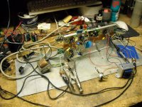
I may finally be starting to get a handle on my distortion setup. I went ahead and set up a ground plane tonight with a sheet of lexan over it (Photo)
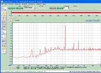
I finally got a FFT of the single ended amp I've been working on (based on the 6N1P for input and 6P1P for output) that the noise floor is starting to look good. 60Hz and it's harmonics are still pretty big though.
I'm going to get some 12" X 66" sections of particle board tomorrow to replace the top of my workbench (it was built in 1981 and needs it). When I do, I'm going to put down a ground-plane under the particle board.
I'm also planning on trying to get a couple more isolation transformers and I'll do a more permanent installation to see if isolating the computer, monitor, etc helps with noise.
Distortion levels are pretty high.
I may finally be starting to get a handle on my distortion setup. I went ahead and set up a ground plane tonight with a sheet of lexan over it (Photo)
I finally got a FFT of the single ended amp I've been working on (based on the 6N1P for input and 6P1P for output) that the noise floor is starting to look good. 60Hz and it's harmonics are still pretty big though.
I'm going to get some 12" X 66" sections of particle board tomorrow to replace the top of my workbench (it was built in 1981 and needs it). When I do, I'm going to put down a ground-plane under the particle board.
I'm also planning on trying to get a couple more isolation transformers and I'll do a more permanent installation to see if isolating the computer, monitor, etc helps with noise.
Distortion levels are pretty high.
Attachments
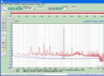
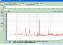
The last plot was taken off a 11:1 divider in the output, so everything shifts up about 3.6dB including the noise floor.
Below 110dB with all the really bad noise gone that I had previously is more acceptable to me.
Hopefully getting a couple more isolation transformers and completing the ground structure will help with the 60Hz and harmonics (especially that thirdand fifth).
Now I can see the IM sidelobes off the 1KHz main, as well as a lot of other related noise.
I think if you move the tub of CoolWhip everything will improve.
Note that you can use the green chassis ground on the front of the IG-18 to connect the generator to the ground of your measurement apparatus.
Note that you can use the green chassis ground on the front of the IG-18 to connect the generator to the ground of your measurement apparatus.
The ground pin is busted off the power connector on the IG-18 (or pop removed it). Either way, I've been connnecting the front panel chassis connection to the bench star ground.
The CoolWhip tub must stay where it is. It supports the keyboard.🙄
The CoolWhip tub must stay where it is. It supports the keyboard.🙄
The last plot was taken off a 11:1 divider in the output, so everything shifts up about 3.6dB including the noise floor.
Below 110dB with all the really bad noise gone that I had previously is more acceptable to me.
Hopefully getting a couple more isolation transformers and completing the ground structure will help with the 60Hz and harmonics (especially that thirdand fifth).
Now I can see the IM sidelobes off the 1KHz main, as well as a lot of other related noise.
It's looking much better for sure.
An 11:1 divider would give you 20.8db insertion loss, which is roughly what you see in the FFT plots.
db = 20* log10(Vout/Vin)
Cheers,
Michael
Last edited:
I'm reorganizing my bench, and have 48" by 10" of copper sheet that I don't have a use for since I quit home brewing (used to make stuff out of it). So I figure I might as well cut it in half and make a 24" X 20" ground plane under the top surface of the bench. This I'll tie to my star ground.
Next up it the isolation transformers. One has a shield tied to frame (Triad N-54M, 150W). I presume that frame in turn should be tied to green wire ground (earth) of the three prong plug. Currently there is only a two prong plug on it so I suspect I need to change this.
The 600W transformer (UTC R-75) and I'm still trying to find if it has a shield. Statements on the net say it has a shield but I've found no catalog specifying so.
Will a ground loop between monitor and computer make a difference? ie can I power both from one transformer or should I isolate them from each other since they are grounded together through the monitor cable? I guess I could break the ground in the shield at one end to see what happened.
Finally, does it matter if I make the new 3 wire cables to the input of the isolation transformers 6' long vs shorter? Currently they are pretty short (1'). Commercial transformers look like they have 5-6' cords on each end which implies it won't matter.
- Status
- Not open for further replies.
- Home
- Amplifiers
- Tubes / Valves
- THD, s/n and IM noisy measurements