I am using audio interface to measure THD of the amplifier and I run ARTA on my PC.
When I connect amp out to the input of the audio interface I get a lot of interference.
Is there a proper way to do this?
Below is the schematics how I currently have it:

I am using Focusrite Scarlett 2i4 audio interface:

When I connect amp out to the input of the audio interface I get a lot of interference.
Is there a proper way to do this?
Below is the schematics how I currently have it:
I am using Focusrite Scarlett 2i4 audio interface:
Last edited:
When I connect XLR pins 2 and 3, the interference is gone. But the level is very low after that. Not sure what to make of it.
tried that, but the interference is still presentInstead connect pins 1 and 3.
I'm guessing it's a grounding issue and will take some transformer isolation between the amp and your audio interface.
Many direct boxes have 30or more db of input pad and transformer balanced outputs.
Many direct boxes have 30or more db of input pad and transformer balanced outputs.
The thing is I did not even connect the attenuator and load resistor to the amplifier at all.I'm guessing it's a grounding issue and will take some transformer isolation between the amp and your audio interface.
Many direct boxes have 30or more db of input pad and transformer balanced outputs.
What is your audio interface wanting to see as an input? If it is balanced line input you are not supplying that,The thing is I did not even connect the attenuator and load resistor to the amplifier at all.
I think what Rayma was saying on the XLR line to the interface was to tie pins 1 and 3 together, is that what you did?
A bit of a cross post. I explained the issue here: https://www.diyaudio.com/community/...hat-beginner-tools-to-get.388418/post-7233652

I was able to pinpoint the issue:
It is the output of the audio interface that produces a lot of interference. As soon as I disconnect it from the amplifier (DUT) input, measurement graph clears out.
I might need to use a separate signal generator. Or maybe a different audio interface.
It is the output of the audio interface that produces a lot of interference. As soon as I disconnect it from the amplifier (DUT) input, measurement graph clears out.
I might need to use a separate signal generator. Or maybe a different audio interface.
The way a balanced input should be wired is signal to pin 2 and pin 3 (speaker ground to 3).I am using audio interface to measure THD of the amplifier and I run ARTA on my PC.
When I connect amp out to the input of the audio interface I get a lot of interference.
Is there a proper way to do this?
Below is the schematics how I currently have it:
View attachment 1129894
Pin 1 can be left unconnected or to the amp chassis, but not to any other line.
Do that and all will be clean.
Jan
Most likely the interface has a pseudo balanced input. So, connecting ground to pin #3 doesn't work and taking it to pin #1 makes a ground loop with the ground from the interface output to amp input -assuming you are using the built in sound gen.
Change the lower resistor to 1k - the lower resistor will set the output impedance of your attenuator, the lower this value the better and the less noise it will generate (Johnson noise). Then try disconnecting the earth from the bottom of your load resistor - whoops, just saw that was what Jan correctly stated
Doesn't matter whether it is pseudo or not. Hot goes to 2, cold to 3, 1 to chassis. That's the standard, don't mess with it.Most likely the interface has a pseudo balanced input. So, connecting ground to pin #3 doesn't work and taking it to pin #1 makes a ground loop with the ground from the interface output to amp input -assuming you are using the built in sound gen.
The drawing in post # 1 is wrong.
Jan
Agreed! I just thought that a differential input would work fine when connecting to pins #2 and #3 but OP said that it doesn't.
The way a balanced input should be wired is signal to pin 2 and pin 3 (speaker ground to 3).
Pin 1 can be left unconnected or to the amp chassis, but not to any other line.
Do that and all will be clean.
Jan
Here is another take:
Here are attached results that I am getting when connecting PIN1 and PIN2 of the XLR mic input for the audio interface:
(just so people get the idea of what I mean by interference - it can be seen as "grass" on those graphs)
(just so people get the idea of what I mean by interference - it can be seen as "grass" on those graphs)
Attachments
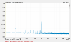
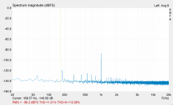
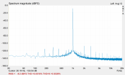
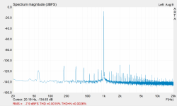
60, 120, 180, 300..... that's 60Hz power line harmonics.seen as "grass"
What happens if you put your hand near or move stuff on the bench? Turn-off all unnecessary lights and loads?
2K, 3K, 4K, 5K... that's expected distortion on a 1KHz tone.
I changed resistor values to 9.1k and 1k.Change the lower resistor to 1k - the lower resistor will set the output impedance of your attenuator, the lower this value the better and the less noise it will generate (Johnson noise). Then try disconnecting the earth from the bottom of your load resistor - whoops, just saw that was what Jan correctly stated
Those should give -20dB attenuation.
Johnson noise should be around -125 dBv.
Most likely the interface has a pseudo balanced input. So, connecting ground to pin #3 doesn't work and taking it to pin #1 makes a ground loop with the ground from the interface output to amp input -assuming you are using the built in sound gen.
According to this article here: https://khronscave.blogspot.com/2019/10/55-focusrite-scarlett-2i2-teardown.html
The NJM2122's in these preamps are wired as the two input opamps in a three-opamp instrumentation amplifier. The third opamp is one half of an NJM4565 (U18 in this case).
- Home
- Design & Build
- Equipment & Tools
- THD measurements - how to correctly wire attenuator for amplifier output and audio interface balanced input?