.... before they are published. Or clearly stated that it is only simulation and not proven in real.Exploring the design space is good but the circuits need to work with real transistors.
Patrick

This is proven Hitachi diagram, used and cloned to humongous proportions, always delivers with so little parts. Input and VAS transistors are not possible to find any more,
We do find them, and also used them a while ago in our Le Monstre 2024.
www.diyaudio.com/community/threads/all-hitachi-lateral-fet-amplifier-for-diy-described-by-paul-kemble.220923/post-8004148
www.diyaudio.com/community/threads/hiraga-le-monstre-2024.413301/post-7695896
Patrick
.
Attachments
Last edited:
Very Much so. It is a ClassicThis is proven Hitachi diagram, used and cloned to humongous proportions, always delivers with so little parts
Such a great topology.
At low voltages, transistor choices become even more fun.
Using higher gain readily available transistors. I have tried B grade everyday BC556B/546B
And at " 1 watt" as posted, distortion is close to the OP post around .0003%
full power holds up to .002%
If everything is tuned to work at lower voltages. This just using standard BJT power transistors.
So normal VBE for bias is employed.
Agree, fun one to play with, with such low part count verses performance
Agree.What more can you wish from symmetry?
As noted the low parts count verses performance often leaves you not needing much more.
I think it is only people that desire dual differential input.
To solve the 2nd gain stage current issues, the parts count goes up.
To help improve the noise issue Hitachi just regulated the power supply.
Instead of using Dual Differential for more noise rejection.
At higher power levels, high frequency THD falls quickly as well too.
Some desire the numbers game, something simulation likely encourages.
Real life, not as much a issue
If people chase it . I do understand.
There is a certain feeling of achievement if THD holds up at high power at high frequency.
Otherwise the performance, with so little parts. Also gives such feelings
Distortion is low: THD 0.00016% at 1 Watt into 8 Ohm.
Ok but how it sound is what matter the most 😎
.
I am working as I said.
But it is not promising. No longer THD 0.00016%. Almost twice that.
And no longer 16 Watt. More like 15 Watt.
I am not happy. Maybe end this project ... 🙁
I could post my revised schematic. Is there anybody who wants this?
But it is not promising. No longer THD 0.00016%. Almost twice that.
And no longer 16 Watt. More like 15 Watt.
I am not happy. Maybe end this project ... 🙁
I could post my revised schematic. Is there anybody who wants this?
If you need a new project, I have an idea: design an amplifier with the lowest possible THD before applying global negative feedback.I am not happy. Maybe end this project ...
Correct, but still you can run very long time at hot bias unnoticed, need to calculate ful pot R scenario.... Good quality pot will probably never fail... It is just small area to improve this design, no drama, but stillSince the wiper and the unused end of the pot are tied together, I would assume that if the pot is an appropriate value, it would merely lead to increased dissipation and not an outright failure.
Exactly, it is versatile. In post about darlingtons from few days ago (think you were there) I showed a picture of Sanken darlingtons, driven by Hitachi amp circuit with pedestrian BC's at input, BD139/140 at VAS and Vbe bias ... works aplomb. PS +-33VIf everything is tuned to work at lower voltages. This just using standard BJT power transistors.
So normal VBE for bias is employed.
Why not, if you have fun, I think many also like to read your SPICE experiments . It is cool fun.I could post my revised schematic. Is there anybody who wants this?
I might have suggestion for next exercise, that I want to start playing when I have time which will never happen:
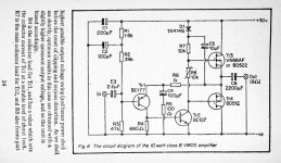
Take one simple but very fast CFB power amp with mosfets, I took first picture from internet, don't know if this one works or not, seems it does if you change mosfets to laterals instead IRF's, of course you can change BC transistors to something better. point is a simple and super fast, forget THD and DC offset:
Than add one classic opamp at input and run global feedback overall with gain bit higher than poweramp itself... see what happens, I think it will satisfy THD needs at many frequencies
If you spice it, I will build it eventually 🙂
That very simple Singleton amp schematic is copied from R.A.Penfold -VMOS-Projects book.
https://www.worldradiohistory.com/UK/Bernards-And-Babani/Babani/83-Penfold-VMOS projects.pdf
https://www.worldradiohistory.com/UK/Bernards-And-Babani/Babani/83-Penfold-VMOS projects.pdf
Attachments
THD says nothing about how it sounds. I've heard amps with 0.0001% that sounded like cr@p, and 2% thd that sounded great.
Last edited:
That would be a challenge.If you need a new project, I have an idea: design an amplifier with the lowest possible THD before applying global negative feedback.
- Home
- Amplifiers
- Solid State
- THD 0.00045% and 15 Watt