I'm using the 1646 and not the 1606, for the 1646 two caps are recommended. (edit: perhaps you asked Dr_EM avout his design?)
Thank you for replay.
You are right I'm asking Dr Em. About his design.
UMarcus, that's a surface mount resistor on the reverse side, 0805 sized, so the application is just as the datasheet shows 🙂
The LM317/337 are easy enough to use, if you have 12V supplies then regulating down to 8.5V is logical since they aren't low dropout regs and anything less than 3V difference is too marginal really. The standard application in the datasheet will work fine and add the capacitor from the adjust pin to ground for lower noise performance. The regs perform best with some capacitance at their inputs, it needn't be as high as 100uF but no harm either! Also you will need capacitors on their outputs, 100uF will be OK here too.
I also much prefer the idea of the analogue volume controller for the reasons you stated. You won't be disappointed with a good implementation of CS3318 🙂
UMarcus, that's a surface mount resistor on the reverse side, 0805 sized, so the application is just as the datasheet shows 🙂
...
Thanks for clarification, i'm also looking for a balanced line driver solution an stumble accros your design
 😀
😀No problem, and I expect to have 2 spare boards so let me know if you're interested in any, they should arrive soon!
No problem, and I expect to have 2 spare boards so let me know if you're interested in any, they should arrive soon!
Many thanks for your offer, i will let you know.
OK, some changes:
1. Reduced the two power caps to 22uf at the advice of DR_EM.
2. Thickened signal traces.
3. Put back the "chassis ground plane", because it made nr 4 easier:
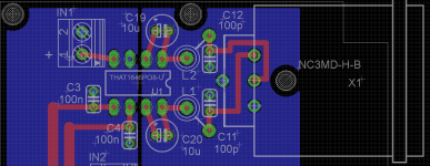
4. Put in the ferrite beads. I´d really like to avoid SMD soldering, so I found a footprint and part in the Adafruit library. I´m using the bead in series after the chips output, and a 100p cap to ground (note: chassis ground) after each bead. I believe this should be correct according to the datasheet, but please correct me if I got it wrong.
5. Increased to 3.5mm connectors, that seems just about right. 🙂
How does this look?
1. Reduced the two power caps to 22uf at the advice of DR_EM.
2. Thickened signal traces.
3. Put back the "chassis ground plane", because it made nr 4 easier:
4. Put in the ferrite beads. I´d really like to avoid SMD soldering, so I found a footprint and part in the Adafruit library. I´m using the bead in series after the chips output, and a 100p cap to ground (note: chassis ground) after each bead. I believe this should be correct according to the datasheet, but please correct me if I got it wrong.
5. Increased to 3.5mm connectors, that seems just about right. 🙂
How does this look?
Attachments
Last edited:
Update: DR_EM helped me complete this design, adding LM337/317 regulators, replacing the beads, and generally cleaning the design up, as well as preparing gerber files for production. Thanks a lot DR_EM and everybody else who have provided comments in this thread, and also thanks to jcga who built similar boards and provided the starting point for me.
The design now looks like this:
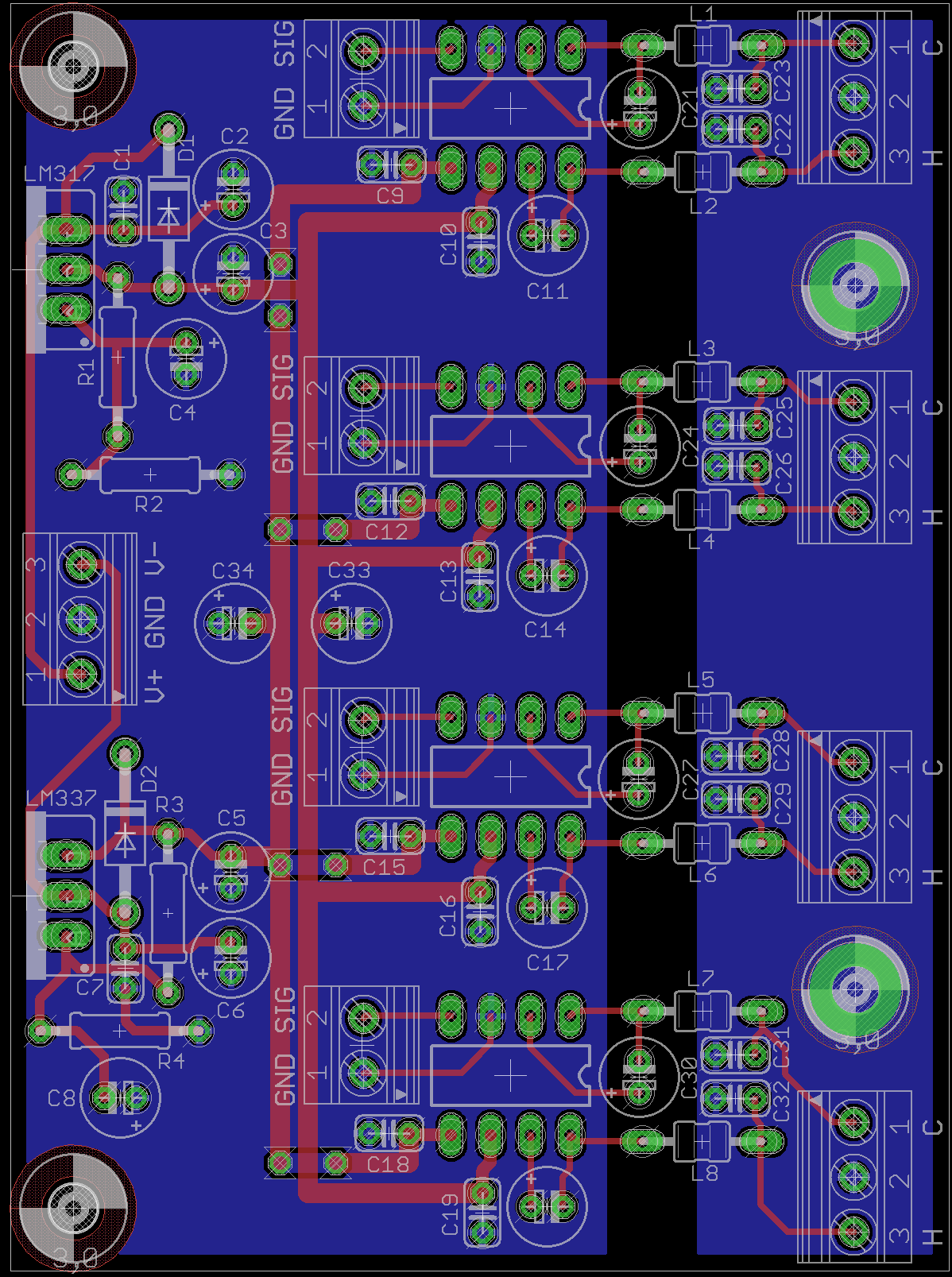
Eagle board:
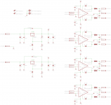
Schematic:

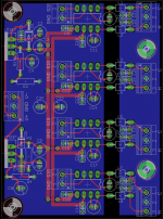
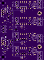
OSH Park rendering (top):

Also included as an attachment to this post is the schematics, board file, bill of materials and gerber files ready for production. I have been looking for such a board for a while, and thought it would be nice if somebody else could just download this one and use it/modify it/make it better etc.
The board is 81x60mm. I have ordered a batch of 3 from OSH Park, but I won´t be able to test it for a while yet (my project is really moving slowly, but piece by piece are falling into place). Will give an update when I do.
The design now looks like this:
Eagle board:
Schematic:
OSH Park rendering (top):
Also included as an attachment to this post is the schematics, board file, bill of materials and gerber files ready for production. I have been looking for such a board for a while, and thought it would be nice if somebody else could just download this one and use it/modify it/make it better etc.
The board is 81x60mm. I have ordered a batch of 3 from OSH Park, but I won´t be able to test it for a while yet (my project is really moving slowly, but piece by piece are falling into place). Will give an update when I do.
Attachments
Last edited:
Thank you! I am working on my own quad THAT 1646 board, and I didn't even notice the 5 kΩ input impedance. I was wondering why another online circuit had a simple voltage follower buffer in front.Also ensure your previous stage can drive the 5K input impedance of these chips, it's not terribly low but some stages won't perform optimally with this, or if you start to parallel things with it.
- Home
- Source & Line
- Analog Line Level
- THAT 1646 PCB - help me review please