Hi All,
Does anyone have any experience with Tezla Audio amps, a TZ-6000.1D, in this case. I am sure there are others that use a similar circuit. The Output MOSFETs are both N and P Channel MOSFETS.
The amp came in with a note that it will not start up and goes into protection. The following has been checked:
I have not been able to identyfy and find any schematics for the driver board, but have been able to determine the following:
- Pins 4, 5 and 12 functions as the integrator.
- Top SOIC8 seems to be a dual N and P channel MOSFET, as far as I can tell
With no feedback (Outputs disabled) the voltage on pin 4 would be above/below the triangle wave with no PWM output. There would be a squae wave at the input circuit and this was expected with not feedback.
With local feedback TL072 pin 1 to 2, I could get the LM319 to produce the PWM as expected. In order to not drive the Outputs, I removed the top SOIC 8 from the driver board.
I am not familiar with this driver bord. Is there a shutdown/mute circuit that I need to confirm is working as expected?
It seems like the oscillations start before the power supplies have stabalized.
Any advice / thoughts?
Does anyone have any experience with Tezla Audio amps, a TZ-6000.1D, in this case. I am sure there are others that use a similar circuit. The Output MOSFETs are both N and P Channel MOSFETS.
The amp came in with a note that it will not start up and goes into protection. The following has been checked:
- No blown Power Supply (PS) MOSFETs / Gate resistors
- PS drive looks fine for all PS Sections
- It is a regulated PS, that reduces PWM once +-100V is reached on rails
- +- 12V Supplies working for preamps. (this does go down to 11.4 when main PS is regulating)
- +- 9 V supplies to the driver card, even though the silk screen indicates +-12V
- No blown Output MOSFETs.
- PS will only fully start up with the Driver Board removed or with drive to the Outputs disabled
- Audio signal gets to the input pin of the Driver Board as expected
I have not been able to identyfy and find any schematics for the driver board, but have been able to determine the following:
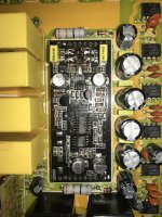
- Bottom SOIC8 is an OPAMP. (A) pins 1,2 & 3 is the audio side, (B) pins 5, 6 & 7 generate the triangle wave
- Middle SOIC14 is likely an LM319 Dual comparator.
- Pins 4, 5 and 12 functions as the integrator.
- Top SOIC8 seems to be a dual N and P channel MOSFET, as far as I can tell
With no feedback (Outputs disabled) the voltage on pin 4 would be above/below the triangle wave with no PWM output. There would be a squae wave at the input circuit and this was expected with not feedback.
With local feedback TL072 pin 1 to 2, I could get the LM319 to produce the PWM as expected. In order to not drive the Outputs, I removed the top SOIC 8 from the driver board.
I am not familiar with this driver bord. Is there a shutdown/mute circuit that I need to confirm is working as expected?
It seems like the oscillations start before the power supplies have stabalized.
Any advice / thoughts?
Attachments
There is a diagram for a similar model driver board but it's not identical. There is no IRF7319.
https://www.diyaudio.com/community/threads/again-with-the-dlogixs-dlm4500.299926/post-6947617
Are you limiting the current input? Yet another version had an excessive current draw on startup and caused some confusion about its status when startup current was limited. Pulsing the remote would allow the rail caps to charge and eventually allow the amp to power up (on the bench).
Hi Perry, yes I am limiting current to 10A. I have also seen cases where this limited amps from starting up and pulsing the remote allowed the rails to build, exactly like you said. However, in this amp once the rail has built to about +-20 V and switching starts, it goes down. I will try building the rails more carefully with shorter pulses and see if that helps.
As always, thanks!
As always, thanks!
I thought I had a reference amp for these but I can't find it. Do the solder connections on the outputs look factory (flow-soldered)?
Thanks for looking Perry. Yes the amp is definately factory. I could not see anything that made me think that it has been worked on before.
After resoldering the SOIC8 (IRF7319) back into place, the amp came back to life.
I did replace the TL072 also, but I cannot be 100% sure that the original was the cause. I Don't really like it when I don't have a definative reason why it is working now, but if it survives testing I will get it back out the door.
Thanks for the help Perry!
I did replace the TL072 also, but I cannot be 100% sure that the original was the cause. I Don't really like it when I don't have a definative reason why it is working now, but if it survives testing I will get it back out the door.
Thanks for the help Perry!
Don't forget to twist indctors/transformers as well as pushing on the various components/boards to ensure that there are no intermittent problems.
Hi Perry, I did the pull/push/tap test and the amp kept running, BUT I noticed something.
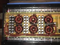
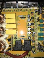
Two of the output inductors are not carrying switching current. While the four that are not circled get warm the other two stay absolutely stone cold. I could also verify no current by sticking my probe into the center of the other four that there is current, incuding the carrier, but the lower two has nothing.
Thoughts? I would really prefer not to pull the amp out of the heatsink in order to trace their connections. They seem solidly connected while pulling/pushing them.
Last edited:
Can you drill down through the insulation with your scope probe (or scratch it slightly) on the windings to see if there is any oscillation?
Do this (if possible) on the 2 terminal windings on each of the cold inductors.
Do this (if possible) on the 2 terminal windings on each of the cold inductors.
There is no oscillation on those two. I will have to pull the amp apart to look at the bottome side what is going on.
Closing out this tread.
Here is a representation of the circuit. The filter formed by L1-L4 and C1-C4 works really well, with only a low amplitude triangle wave remaining from the R-R Oscillation, as expected. If I had adjusted my vertiacal scale correctly, I would have seen the triangle wave on the input side of L5-L6.
In summary, there is no fault in the filter section of this amplifier.
- Home
- General Interest
- Car Audio
- TEZLA AUDIO TZ-6000.1D Goes into protect