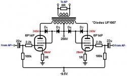
The Tancinco topology was patented in 1964 (US3136766), supposedly as a way to iron out crossover notch distortion in Class B amplifiers, and I've always wanted to give the concept a try. The idea is to add a pair of diodes so that when the anode swings above B+ the screen grid is driven directly from the anode (triode mode), but when the anode swings below B+ the screen is fed directly from the B+ (pentode mode). In theory this would give you the output power of pentode mode but a somewhat lower output impedance and the softer cut-off characteristic of triodes, which should suppress crossover defects. I've always wanted to try it out, so here are some quick and dirty results.
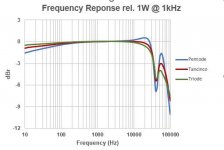
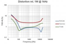
Test circuit below using a pair of 6P14P (basically EL84s) with an 8k : 8R transformer and regulated power supplies. Tubes biased to class-AB datasheet conditions. I have presented results for ordinary pentode and triode mode too by fitting D1/D2 alone (triode), or D3/D4 alone (pentode), or all four diodes for Tancinco mode. Tested on an Audio Precision System 1, 80kHz bandwith.
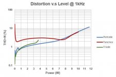
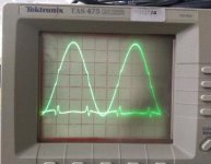
Results for Tancinco are dire. The diodes introduce a painful discontinuity into the signal which is worst at small signal levels; the oscillogram shows a 1V output signal together with the distortion residual. Tancinco tested the idea with vacuum diodes which of course would soften the switching, but I still kinda doubt he actually saw his claimed benefits even in 1964. Anyway it was fun to finally try the idea out.
Output impedance:
Pentode = 43 ohms
Tancinco = 9.5 ohms
Triode = 5.1 ohms
Input level (grid to grid) for 1W output:
Pentode = 9.4Vpp
Tancinco = 15Vpp
Triode = 24Vpp
Test circuit below using a pair of 6P14P (basically EL84s) with an 8k : 8R transformer and regulated power supplies. Tubes biased to class-AB datasheet conditions. I have presented results for ordinary pentode and triode mode too by fitting D1/D2 alone (triode), or D3/D4 alone (pentode), or all four diodes for Tancinco mode. Tested on an Audio Precision System 1, 80kHz bandwith.
Results for Tancinco are dire. The diodes introduce a painful discontinuity into the signal which is worst at small signal levels; the oscillogram shows a 1V output signal together with the distortion residual. Tancinco tested the idea with vacuum diodes which of course would soften the switching, but I still kinda doubt he actually saw his claimed benefits even in 1964. Anyway it was fun to finally try the idea out.
Output impedance:
Pentode = 43 ohms
Tancinco = 9.5 ohms
Triode = 5.1 ohms
Input level (grid to grid) for 1W output:
Pentode = 9.4Vpp
Tancinco = 15Vpp
Triode = 24Vpp
Attachments

Here is the concept needed, active-ultralinear.
https://www.diyaudio.com/community/...dislike-ultralinear.98330/page-4#post-1176732
Should work well for low screen V output tubes, since it can just run off the UL taps for power, for the differential control tubes.
https://www.diyaudio.com/community/...dislike-ultralinear.98330/page-4#post-1176732
Should work well for low screen V output tubes, since it can just run off the UL taps for power, for the differential control tubes.
Last edited:
There was a thread recently (maybe 6 months ago) where something similar was proposed. Unfortunately I don't recall the title. Hopefully they will drop in to comment.
For a low screen V output tube, most of the screen current can come from the UL tap ( through the regulator load resistor ), so the active regulator tube only needs the ability to suck off enough current for the linearity correction (variance from straight UL ). A small tube like the 6BN11 dual pentode -might- be enough. Otherwise a pair of 6CL6/ 6197, 6HB6 or 12HL7 should be adequate. If the UL tap gets too low in voltage for the regulator to operate (at least it will be drawing minimum correction current then), then some diodes for the regulator load R top, like the Tancinco, could be put in (between UL and B+). Maybe put a series resistor in with the diodes going to B+ so that no Tancinco like "kink" is developed. A high Ri (or Rp) pentode for the regulator should not notice the diode UL/B+ commutation activity anyway.
For a low screen V output tube, most of the screen current can come from the UL tap ( through the regulator load resistor ), so the active regulator tube only needs the ability to suck off enough current for the linearity correction (variance from straight UL ). A small tube like the 6BN11 dual pentode -might- be enough. Otherwise a pair of 6CL6/ 6197, 6HB6 or 12HL7 should be adequate. If the UL tap gets too low in voltage for the regulator to operate (at least it will be drawing minimum correction current then), then some diodes for the regulator load R top, like the Tancinco, could be put in (between UL and B+). Maybe put a series resistor in with the diodes going to B+ so that no Tancinco like "kink" is developed. A high Ri (or Rp) pentode for the regulator should not notice the diode UL/B+ commutation activity anyway.
Last edited:
- Home
- Amplifiers
- Tubes / Valves
- Testing The Tancinco Topology