Current output dacs are bounded by the allowable compliance voltage at the output before the dac linearity is degraded. In the 1794 I take the practical upper limit to be about 100mVpk for this reason. I'm running at about 1/3 of this (including half scale offset..)
Can you show me how you came up with 100mVpk? It's been shown on this thread that 50 ohms input impedance is the maximum for this DAC before distortion increases, so 50ohms*7.8mA = 390mVpk. Granted, lower is better, but I think there's some wiggle room for this. My circuit shows at least 100mVrms on the primary side with full 7.8mA input and a 30 ohm damping resistor, but it's very dependent on the damping resistor value, obviously, since it changes the input impedance directly.
Can you show me how you came up with 100mVpk? It's been shown on this thread that 50 ohms input impedance is the maximum for this DAC before distortion increases, so 50ohms*7.8mA = 390mVpk. Granted, lower is better, but I think there's some wiggle room for this. My circuit shows at least 100mVrms on the primary side with full 7.8mA input and a 30 ohm damping resistor, but it's very dependent on the damping resistor value, obviously, since it changes the input impedance directly.
Just being overly conservative, possible/probable math error (yeah) as well. I would take the value listed at 50 ohms as reasonable, and if there are no measurable or audible artifacts at this level then there shouldn't be an issue.
Active thread?
Hi Guys,
I find this thread really helpfull and am curious about the latest results...?
Is this topic continuing on another thread?
Thanks
Derek
Hi Guys,
I find this thread really helpfull and am curious about the latest results...?
Is this topic continuing on another thread?
Thanks
Derek
Hi Guys,
I find this thread really helpfull and am curious about the latest results...?
Is this topic continuing on another thread?
Thanks
Derek
Regarding using the PCM1794A in single-ended passive (resistor) I/V configuration, I can affirm Sergio's suggestion to use an I/V resistor value as close to 50 ohms as is practical on the utilized output phase, while connecting the non-utilized oppositely phased output pin directly to ground. The sound subjectively becomes more relaxing, and more tightly focused particularly in the bass, as compared to utilizing higher I/V values and/or connecting the non-utilized output phase to ground via a matching resistor. At least, that is what I head via my homebrew PCM1794A DAC. 🙂
Regarding using the PCM1794A in single-ended passive (resistor) I/V configuration, I can affirm Sergio's suggestion to use an I/V resistor value as close to 50 ohms as is practical on the utilized output phase, while connecting the non-utilized oppositely phased output pin directly to ground. The sound subjectively becomes more relaxing, and more tightly focused particularly in the bass, as compared to utilizing higher I/V values and/or connecting the non-utilized output phase to ground via a matching resistor. At least, that is what I head via my homebrew PCM1794A DAC. 🙂
Ken, I've been fiddling around since you posted a link to this thread over in Doedes' DDAC1794 thread. Most interesting..... I've verified 2nd harmonic from the pos out is reduced by ~3db with the unused neg out directly grounded, rather than being tied to ground by the same size I/V resistor used for the pos out. Most curious. And as you point out there is a "tightening" of the sound from the pos out by directly grounding the non-utilized neg out.
Hi Guys,
I find this thread really helpfull and am curious about the latest results...?
Is this topic continuing on another thread?
Thanks
Derek
I have built a stereo pair of IV converters using the circuit I posted here and circuit boards from Pad2Pad. I have tested it using a good quality input transformer and found that it did not add any distortion that I could see. I have not hooked it up to the DAC yet. I ran into a problem when I realized that the Chinese boxes I had were not RF resistant. They hard anodized all of the panels so none of them conduct. I have to decide to either modify them or use different boxes.
Hi, Clive,
You can also see in Sergio's post #13 of this thread that grounding the un-utilized phase output pin significantly lowers the 3rd harmonic.
Another potentially fruitful activity is to try directly (A.C. coupled) connecting the passive I/V output to your power amp. No intervening DAC active stages, no preamplifier box at all. My DAC puts out 200mVRMS full scale via 75 ohm passive I/V resistors, and while a little lower in volume than I would sometimes like (being recording dependant) the sound quality advance was large in my system. That's right, I don't presently have any volume control or input switching in my system, just a pair of interconnects between the DAC and power amp. However, the sound quality improvement is worth the inconvenience for the moment. The 200mV DAC output seems a good compromise for usability with my power amp and 93dB sensitive speakers just by happenstance. My preamp is a discrete JFET based unit from the defunct Forte audio (a spin-off of Threshold), and I think it would be fair to say I was quite surprised by the level of improvement without it.
Last edited:
Thanks guys
Thanks Guys,
Really interesting and ties in well with the DDAC1794 plans I have... Currently
(pun intented!) I am using various ESS DAC's but I have a feeling that some sort of NOS DAC may be where I end up.
Ken,very interesting re direct connection... I hope to implement a no loss digital volume control in the PC source, I need Eq so as long as I have enough "spare" resolution headroom I should be able to test your method and still have volume control.
Last question please! It's off topic but just in case...
I am trying to find a way to use studio grade plugins ( Blue Cat, Fab Filter etc) with JRiver 18 as the music source & VST host with JPlay running in hibernate mode and controling the whole operating system.
So far nobody has found a way to make it work with one mother board... Any ideas?
Adding a second DSP board post main board should work but then I will reduce the ( very audible and worthwhile) sonic benefits hibernate mode gives...Chicken and egg!
Thanks again
Derek.
Thanks Guys,
Really interesting and ties in well with the DDAC1794 plans I have... Currently
(pun intented!) I am using various ESS DAC's but I have a feeling that some sort of NOS DAC may be where I end up.
Ken,very interesting re direct connection... I hope to implement a no loss digital volume control in the PC source, I need Eq so as long as I have enough "spare" resolution headroom I should be able to test your method and still have volume control.
Thanks again
Derek.
Yes, the PCM1792 actually features a high resolution digital volume control, but I believe that you have to make use of the internal digital interpolation filter (so, no NOS) to utilize the volume control.
How about raise the ground reference in order to get rid of the capacitor?
Hi, Clive,
You can also see in Sergio's post #13 of this thread that grounding the un-utilized phase output pin significantly lowers the 3rd harmonic.
Another potentially fruitful activity is to try directly (A.C. coupled) connecting the passive I/V output to your power amp. No intervening DAC active stages, no preamplifier box at all. My DAC puts out 200mVRMS full scale via 75 ohm passive I/V resistors, and while a little lower in volume than I would sometimes like (being recording dependant) the sound quality advance was large in my system. That's right, I don't presently have any volume control or input switching in my system, just a pair of interconnects between the DAC and power amp. However, the sound quality improvement is worth the inconvenience for the moment. The 200mV DAC output seems a good compromise for usability with my power amp and 93dB sensitive speakers just by happenstance. My preamp is a discrete JFET based unit from the defunct Forte audio (a spin-off of Threshold), and I think it would be fair to say I was quite surprised by the level of improvement without it.
Attachments
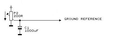
How about raise the ground reference in order to get rid of the capacitor?
Unfortunately, that 1000uF electrolytic capacitor is still in the A.C. circuit. So, while you can manually null any D.C. offset, the cap. establishes an A.C. ground, completing the circuit for signal current return and is therefore directly in the signal path.
Last edited:
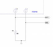
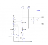
Looking at 2A3SET picture I thought about this. It resolves the dc problem ,
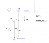
R3 is a 1K trimmer for nulling DC output.
C1 is optional and serves for filtering the high frequency trash ,
Ken, the problem that you experience with your preamplifier is maybe caused by the high frequency trash, i recommend that you try to put a capacitor in parallel with the 50 ohms resistor the value should be between 10nf and 22nf.
Attachments
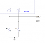
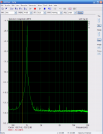
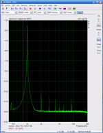
I searched for pictures of the tests that i have performed on the pcm1794 and find a fft from this circuit, unfortunately I do not have a test with two resistors of 25 ohms , but i predict the distortion is inferior with 25 ohms.
As expected from a balanced circuit the pairs harmonics are attenuated.
As expected from a balanced circuit the pairs harmonics are attenuated.
Attachments
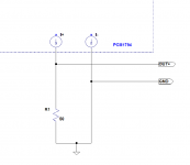
So , based on the last two posts, I predict that the distortion in the circuit from post 72 is equal to the single 50 ohms resistor , But with less second harmonic. The output A.C. voltage is also equal.
of course , with the added benefit that we do no longer need a capacitor at the output 🙂
of course , with the added benefit that we do no longer need a capacitor at the output 🙂
Attachments
Last edited:
Sergio,The circuit in post 72 only work in mono. sorry guys ,my mistake 🙁
Even so, I still find your FFT plots interesting in that for either mono or stereo mode, the PCM1794A will generate equivalent levels of odd order distortion in either single-ended or differential passive I/V output configuration if the same sum total I/V resistance value is in place. Not only would that establish the same net source resistance for either configuration, it also establishing the same fullscale passive I/V net signal voltage amplitude. The cancellation of even order distortion appears to be the only significant performance difference between the two configurations.
One of the system design implications of the above is that while differential drive can give twice the signal amplitude, that comes with a non-proportional increase in odd order distortion percentage.
Last edited:
Ken, That is the case when using passive resistor I/V converter, but with low impedance values like when one use a active I/V converter, the odd harmonics are also cancelled , as i have shown in post #7. But I must admit that using a 50 ohms or less also have very good linearity.
I was not talking about mono or stereo mode. The circuit that I post in #72 just dont work with two channels , because the preamplifier GND is common to the 2 channels. It was a mistake.
I was not talking about mono or stereo mode. The circuit that I post in #72 just dont work with two channels , because the preamplifier GND is common to the 2 channels. It was a mistake.
Last edited:
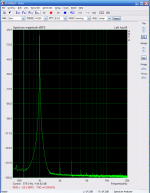
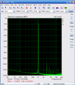
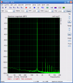
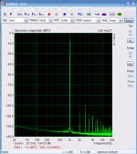
Yesterday, I was making some tests in a I/V converter that I am working on , and remind me, that I never post pictures from 96Khz and 192Khz in this thread, so here they are, for future reference .
First 44Khz second 96Khz and third at 192Khz, all of them 24bits at -1dB of full scalle (2Vrms).
This test was made with a balanced connection.
the distortion at 44khz is only 0.00022% then double to 0.00044% at 96Khz and double again to 0.00088% at 192khz.
First 44Khz second 96Khz and third at 192Khz, all of them 24bits at -1dB of full scalle (2Vrms).
This test was made with a balanced connection.
the distortion at 44khz is only 0.00022% then double to 0.00044% at 96Khz and double again to 0.00088% at 192khz.
Attachments
- Home
- Source & Line
- Digital Source
- Testing the pcm1794