Hey Guys,
My AC millivoltmeter was just delivered today, and I have a question regarding measuring gain and frequency response of my preamp.
For the gain, can I simply use a 1K sine wave from my function generator, set to say 0.1VAC, and then measure the VAC at the output? When I do this, I get 0.67VAC. Would this then tell me my gain is 6.7???
And for the response, do I use a similar setup where I set the output voltage on the fxn.gen. to 0db on the millivoltmeter, and then measure at various frequencies? What is the reference frequency in this application?
Thanks,
Bryan
Never trust what your oscillator tells you in terms of voltage unless you know exactly how it works. Always measure its output voltage when connected to your amplifier using the same meter that you use to measure the output of your amplifier.
There doesn't need to be a reference frequency for your millivoltmeter - it responds equally at all frequencies. 0dB probably refers to 0.775Vrms.
There doesn't need to be a reference frequency for your millivoltmeter - it responds equally at all frequencies. 0dB probably refers to 0.775Vrms.
Overall gain is really pretty useless. Depends on volume control anyway (if applicable). A better form is X volts input for full power of Y watts output at frequency Z.
I always just eyeball gains in my designs. Output takes a certain amount of drive voltage so driver and preamp need a certain amount of gain, then add like 10x more for NFB and it'll be about right. I don't have a target value. Not sure if that'll tell you anything though...
For frequency response, be certain that the signal generator is flat, as well as the voltmeter! My DMMs start dropping off at 3kHz making them utterly useless for testing frequency response where things get interesting (>10kHz). Learn how to take RMS readings on the oscilloscope.
If the generator isn't flat you'll have to readjust its output for each frequency to be sure. Then measure output voltage, divide by input and that's your overall gain at that frequency.
-3dB points are where power (and thus audible intensity) drops by half; voltage gain will be down by -3dBV = factor of sqrt(2)/2 (.707x).
Tim
Response
We normally use 1KHz.What is the reference frequency in this application?
Hi,
If you have a sig gen and a scope you could make good use of
a suare wave (preferably with a fast rise and fall time).
looking at the shape of the wave @ the output can reveal a
multitude of sins.
eg:
high frequency loss, low frequency distortion, phase shift,
high frequncy loss with low frequncy phase shift, to name only a few.
a strong square wave (meaning rise and fall time)
is a complex waveform that contains many frequncies and harmonics, so can be used to test for a multitude of problems
Regards stormy.
Hey stormy,
Thanks for the input. Do tell, what should I be looking for with the square wave. I've tried this before, but dont see much deviation from the source.
Any specific frequencies I should focus on? What do the waves at the output look like when revelaing the "multitude of sins?"
Thanks,
Bryan
Thanks for the input. Do tell, what should I be looking for with the square wave. I've tried this before, but dont see much deviation from the source.
Any specific frequencies I should focus on? What do the waves at the output look like when revelaing the "multitude of sins?"
Thanks,
Bryan
Hi, Bryan
I have a set of pictures of square waves ilustrating non linearities
and frequency and phase problems , unfortunately my scanner
is not in a posotion to use @ the moment.
as for the frequency to test under 1k is fine as i mentioned earlier
a square wave is made up of complex frequencies and harmonics
when adjusting you scope probe make shure that the sqaure is
as sqare as you can get it using the adjustment on the probe itself.
if you gen has slow rise and fall times then this may not be a good test for you.
I will try find some waveform pics on net for you to look @
failing that i will have to draw in paintshop for you (hope I dont have to go this far) lol.
regards stormy
The basic idea is:
A perfectly square wave is heaven. But we can never achieve this condition so here's the run-down on problems:
Top surfaces:
If sloping down towards zero, it shows a natural phase-shift + LF cut. Usually negligible at 2kHz but very distinct at say, 100Hz. A 5 or 10Hz squarewave will be sloped down so much you just get a train of pulses (the amp is acting as a differentiator). This can be a useful test to show LF instability which will manifest itself as bouncing on this pulse.
If sloping up, you've got an inverse phase shift...I've never seen this before so I don't know what you screwed up. 😉
Ideally this is flat horizontal.
Around the leading and trailing edges:
Rise time - defined as the period during which the squarewave traverses from 10% to 90% of its voltage level. For tube amps this is usually like an RC charging curve, whereas transistor amps tend to be slew rate limited (slew is the rate of voltage rise over time, how fast the waveform rises or falls). I think!
Undershoot - after the rising edge it just lazily levels off (usually with some sort of curve to it) to the maximum level. This may be satisfactory but if it seems too slow you should check capacitances in the circuit. A slow response indicates a lot of loading (parallel) capacitance on the signal.
Overshoot or ringing - the rising edge produces significant harmonics and these will excite any resonances (peaks) in the amplifier's response. Say you have an undamped pentode amp: the OPT might have a parallel resonance at 30kHz (where parasitic capacitance's reactance = leakage inductance's reactance) which causes a rise of say 3dB above the midband level. Well a squarewave would show a strong ringing of this frequency, starting with maximum amplitude after the rising corner and falling off exponentially. Just like ringing a bell. In a critically damped amplifier (the usual strategy to combat this particular effect being a zobel across the OPT primary and a "speed-up" capacitor on the NFB resistor) there will be no rise in gain at this frequency, nor any overshoot. If there is maybe 1dB rise instead, you'll get a little tit of overshoot, maybe 1 full cycle's worth visible before it's utterly damped out.
For really bad ringing, though it still is a leading edge characteristic, it may indeed cover the entire top of the waveform. (Note that a short blip will turn into a full top-covering ring with 10 or 20kHz squarewaves. The amplifier just isn't fast enough to reproduce such signals accurately. The harmonics are 30 to 60kHz anyway so don't worry about it.) If your amplifier is this bad, I guarantee it will oscillate if you try adding NFB!
Tim
Hi,
thank you Sch3mat1c
Bryan does this mean I dont need to get paintshop pro out
or would you like to see some of these waveforms?
Regards stormy
thank you Sch3mat1c
Bryan does this mean I dont need to get paintshop pro out
or would you like to see some of these waveforms?
Regards stormy
EC8010 said:Never trust what your oscillator tells you in terms of voltage unless you know exactly how it works. Always measure its output voltage when connected to your amplifier using the same meter that you use to measure the output of your amplifier.
There doesn't need to be a reference frequency for your millivoltmeter - it responds equally at all frequencies. 0dB probably refers to 0.775Vrms.
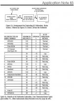
never trust your a.c. millivoltmeter -- here's the analysis which Linear Tech did for Application Note 83 -- "Performance Verification of Low Noise Low Dropout Regulators" What is a little surprising is that the Agilient 34401A performs so poorly in this test. Interesting further -- Linear obsoleted the LT1008 thermal converter.
Attachments
time domain
This may be useful for understanding square wave analysis.
Time Domain Audio Measurements
Michael
This may be useful for understanding square wave analysis.
Time Domain Audio Measurements
Michael
Don't trust anything!
Yes, I should also have said don't trust your meter! Most <£100 DVMs measure AC very poorly, whereas older equipment based on moving coil meters can be quite good. The AVO8 is useable to 15kHz. My (second-hand) Levell microvoltmeter is -3dB at 3MHz, and I used to have an ancient Marconi meter that was flat (-0.1dB) to 50MHz.
Don't forget that a 20MHz oscilloscope means -3dB at 20MHz.
You really need to know the limitations of your test gear.
To be fair, measuring noise is a very tough test, and it is perfectly possible for two meters to give different (legitimate) readings.
Re: time domain
Hi,
thanx for posting this link, it ilustrates some good examples,
and saves me making a fool of myself in paintshop hehe
i hate paintshop :0)
Regards stormy
audiobot said:
Hi,
thanx for posting this link, it ilustrates some good examples,
and saves me making a fool of myself in paintshop hehe
i hate paintshop :0)
Regards stormy
Re: Don't trust anything!
Not necessarily. I seem to remember my 475 is rated -1dB at 200MHz...
Tim
EC8010 said:Don't forget that a 20MHz oscilloscope means -3dB at 20MHz.
Not necessarily. I seem to remember my 475 is rated -1dB at 200MHz...
Tim
In general, if not specified. I could spec my amplifiers at 5Hz to 200kHz if I wanted, but it would be +1dB/-20dB in reality. MOST BW specs have variation at -1.5, -3 or -6dB (and little care towards any rises).
Lemme see...ok. Manual seems to imply -3dB point for BW (in any position).
Tim
Lemme see...ok. Manual seems to imply -3dB point for BW (in any position).
Tim
Attachments
Hi there..... I've enclosed some links for those who need volts/dBu's/dBm's clarifying:
Starting out in test ? get hold of this lot......
At www.sowter.co.uk ........ scroll down to Decibels:
www.rane.com/note145.html
www.jimprice.com/prosound/db.html
learn and memorise the lot.....
rich
Starting out in test ? get hold of this lot......
At www.sowter.co.uk ........ scroll down to Decibels:
www.rane.com/note145.html
www.jimprice.com/prosound/db.html
learn and memorise the lot.....
rich
- Status
- Not open for further replies.
- Home
- Amplifiers
- Tubes / Valves
- Testing response....