I HAVE searched (for once  ), but i could not find any info on testing op-amps.
I have approx 50 TL081s, which i was given, "as sold" so to speak, as half of them are probably dead. does anyone have a simple circuit (to be built on a breadboard) that i could use to test the opamps?
any help appreciated.
thanks in advance,
Matthew
), but i could not find any info on testing op-amps.I have approx 50 TL081s, which i was given, "as sold" so to speak, as half of them are probably dead. does anyone have a simple circuit (to be built on a breadboard) that i could use to test the opamps?
any help appreciated.
thanks in advance,
Matthew
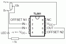
With that circuit, the led will probably just stay on. I would suggest wiring pot from +ve to -ve rails, adding 10k resistor from pot wiper to pin2, and 10k resistor from pin2 to pin6, and another led in parallel to existing led but opposite polarity. This will give an inverting amplifier with gain of 1. With the pot in the middle, both leds should be out - varying the pot one way or the other will cause one of the leds to vary in brightness with the pot.
Cheers
Cheers
Centauri said:With that circuit, the led will probably just stay on. I would suggest wiring pot from +ve to -ve rails, adding 10k resistor from pot wiper to pin2, and 10k resistor from pin2 to pin6, and another led in parallel to existing led but opposite polarity. This will give an inverting amplifier with gain of 1. With the pot in the middle, both leds should be out - varying the pot one way or the other will cause one of the leds to vary in brightness with the pot.
Cheers
thanks.

richie00boy said:...adding of course that pin 3 is tied to 0V for the reference of the amp
what do you mean by that?
what do you mean by that?
That unless you connect that pin to 0V, the circuit will just go mad as it has no ground reference.
PS hope your crazy chip amp sub thing worked out OK
richie00boy said:
That unless you connect that pin to 0V, the circuit will just go mad as it has no ground reference.
PS hope your crazy chip amp sub thing worked out OK
i realise this. i do have some basic knowledge of electronics.
yes, it is working fine. i still havent sorted out a permenant power supply yet though.

comments?
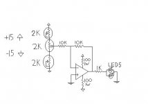
This is taking a couple of ideas from elsewhere as well...
the 2k pot sets the Vin. the other two are for adjustment. the 100R resistors are to protect the power supply from shorted devices being tested.
I am in the process of building this from junk-bin parts. Actually, I'm ~trying~ to make a quad opamp tester, with all 4 inputs from the one pot.
Any comments or suggestions for improvement?
Attachments
An externally hosted image should be here but it was not working when we last tested it.
I don't mind attaching a 20k .jpg! I'm a noob here, and somehow being under moderation doesn't mix with attaching images directly. I was pretty frustrated or I would have put it this way to start. I have at least ten thousand (yes that's right) UBB message board posts under my belt at Fxtreme, OT.net, Ramchargercentral, Carsound.com, sharkracing, and a couple others...but that's all a couple years ago. Moderators haven't given me an *edit* button yet, or the other messages would have been gone already...
- Status
- This old topic is closed. If you want to reopen this topic, contact a moderator using the "Report Post" button.
- Home
- Design & Build
- Parts
- Testing Opamps