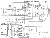
Got a Trace Elliot V4 Bass amp (4 x KT88, B+ = 680V). It claims 220W output, which for bass, I take to be down to 40Hz.
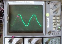
a KT88 lost vacuum and blew the mains(!) fuse. This may be to do with the HT fuse being T2A. with new valves set up at 30mA, the amp works unless you play hard, when it breaks up. A sine wave test into 8 Ohm resistive dummy load shows the waveform just disappears to zero.
Suspecting the output trafo, I tried connecting 28V 50Hz from a high-power toroid to the 8 ohm tap. A 47 Ohm resistor to limit current. Primary totally disconnected from anything. The OT pulls the output down to 21V the other side of the 47 Ohm, which sounds like 140mA rms @ 50Hz to my calculator. The exact same setup measured only 40mA in the OT of a 100W PA amp.
Seeing how 225W is ~42V rms into 8 Ohms, I'm assuming the OT is fried.
Am I missing anything? A new 220W OT is expensive, & I wanted to be sure.
THANKS!
Rod --
It sure sounds bad to me. You didn't provide any info as to the power supply's behavior when you were conducting you sine wave tests. I assume all the voltages were holding up well, and it wasn't the power supply collapsing under load? I wouldn't think that would be the problem, but as you say, a replacement for this sucker will be expensive.
One last acid test I would perform would be to monitor the current draw of the output stage under a power output test. Assuming there are no parasitic oscillations going on, lots of current draw with the application of signal, but little power output being developed pretty well puts the last nail in the coffin!
Dave
also check the balance of the primary sections. the CT should be exactly CT some OT's go bad and one side of the primary will be 2-3 volts or more lower and this can cause problems.
Sounds like a classic shorted turn.
Last resort: check there's nothing jammed between the former and core that could provide a s/c. Older transformers often wern't designed with creepage nor former cheeks and the windings with time get physically closer to the ferrous.
richy
Last resort: check there's nothing jammed between the former and core that could provide a s/c. Older transformers often wern't designed with creepage nor former cheeks and the windings with time get physically closer to the ferrous.
richy
Attachments
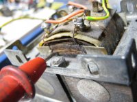
Think you made the right call from the jump on this one Rod. With the drop across the 47 ohm resistor you posted earlier, that means the transformer is giving up at a little over 55 watts. A zero impedance drive may have gotten a few more watts, but there is no way that waveform should be clipping at that level and frequency for the power it's supposed to handle. I think you can safely pony up for a new one, although Rich made some great points. Any chance of a visible short that can be repaired? It's probably wishful thinking, but certainly worth one last look before the order is placed!
Dave
Dave
Shorted section in the o/p tranny forcing flat top saturation. Try backing off the volts and see if decent sine wave returns is a sure sign.
Otherwise it's a duffer. To reconnect to amp with a good tube would be suicide.
A fast 500mA fuse in the center tap is a good insurance policy !
Guitar bass = 40Hz cutoff.
richy
Otherwise it's a duffer. To reconnect to amp with a good tube would be suicide.
A fast 500mA fuse in the center tap is a good insurance policy !
Guitar bass = 40Hz cutoff.
richy
Caught it. Used a 10W practice amp connect via 47R to a little mains trafo. Primary of this trafo to suspect OT secondary 8 ohm tap.
Sine signal from MD player to amp, turn it up - up to 20V, no distortion, above that the crushed waveform as before.
Thanks for everyone's help and suggestions! Just got to find a replacement OT that can take the crazy high B+ in this amp (yes, it really does 700V unloaded, with octal socketed tubes)! Any ideas welcome for a robust trafo.
The B+ is high, but not beyond what any well built transformer should be able to handle. Is the original one still available by chance? If you have to go the after market route, I would think the bigger issue will be finding one of an appropriate power and impedance level suitable for a bass amp. Any idea of what the primary impedance was supposed to be? Sure would be nice to know the original value, although a good set of curves would work, too.
Dave
Dave
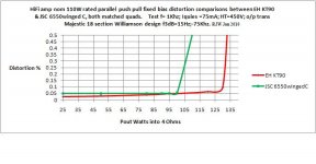
You'll be looking around 2K A-A; Do you really need all that power ? I find modern day KT88's can't take the stick esp at the voltage you quote. If the tranny heater ratings are up to it, I am using EH KT90 in lieu and these are
more power efficient and robust. Entirely your call.
I've enclosed a graph of what 4x KT90 can do compared to 6550C for the same anode load; (the 6550C is virtually power compatible with KT88's, but NOT B+ voltage/screen compatible !)
Note:- Pout for KT90's with a lower B+ have the upper edge: perhaps food for thought for those fitting out a new project.
As such I am fitting EH KT90's in all my amps now.
richy
Attachments
I was originally thinking of about 2K as well for a P-to-P value, but without knowing the screen voltage thought better of putting that out there. Still, to produce that kind of power in (assuming) class AB1 with 4 tubes would require something near that value.
I experimented with KT-90s when they first came out from the Yugo firm that first marketed them. I found them to offer an identical power increase to that which your information indicates, with a notable improvement in THD at 20 Hz, since their higher current construction provided a lower source impedance to drive the OPT with. They are stable and make for an easy and worthwhile upgrade.
In a bass amp, you need all the power you can get, and then some. The 90s might push it close to 250 watts if the supply and OPT can take it. Nice specs on your amp Richy! Thanks for providing the curve.
Dave
The Trace Elliot has a separate power supply for the screens & preamp: 375V unloaded.
The 700V B+ and screen supply have a fuse each: T2A in both cases. I can't see why they should be slow-blow at all, and the screen fuse seems entirely useless!
The KT90 story is an interesting development, Richy - are the EH type reliable now?
thanks
The 700V B+ and screen supply have a fuse each: T2A in both cases. I can't see why they should be slow-blow at all, and the screen fuse seems entirely useless!
The KT90 story is an interesting development, Richy - are the EH type reliable now?
thanks
I wondered as much. The lower screen voltage will move up the required P-to-P impedance somewhat, and in a pentode application where every watt counts, and close match is a must. Based on the power output claims and the B+ level, a rough estimate would put it around 2.4K.
Actually, I find screen fuses to be pretty helpful, as internal arcing within an output tube can involve the screen as well. Granted, when the amp is grossly misloaded at high levels, the transformer's back EMF will cause wicked issues at the plate -- but some extra protection at the screen never hurts either. But slo-blow? No way!
Dave
There was a period when manufacturers were lazy about fitting screen resistors in UL circuits and fixed screen supplies. I've lost many a good tube from a transient instantly destroying the screens. So now I fit 2Watt 68-100 ohm carbon composition types on each o/p tube (beam tetrodes and EH KT90's) and the problem has vanished..
As for the EH KT90, I'm running'em at 90mA each and a conservative 450V+ i.e 40W park where other siblings start moaning red. I purchased them in Jan this year, in regular use, sofar no quies drift. These tubes have stacks of reserve.
With parallel p-p o/p stages around 150W, a fast 500mA fuse in the o/p tranny centre tap, is fine for slam HiFi but for MI and a violent stage the fast 500mA will blow easy. It can get difficult to provide tube protection, but the output tranny is by far the most important item to save. I use a Fast 750mA on the centre tap with my other amp playing trumpet. Important when fitting the fuse,(1.1/4 types) also use a cap 470nF etc on the o/p tranny side to deal with the int fuse arcing.
richy
I wondered as much. The lower screen voltage will move up the required P-to-P impedance somewhat, and in a pentode application where every watt counts, and close match is a must. Based on the power output claims and the B+ level, a rough estimate would put it around 2.4K.
Dave
Good call, Dave. I measured the ratio with only 6V and found it to be 2500 Ohms A-A. The ratio is fine on both sides till the volts go up, then it breaks over.
Interestingly, Later Trace Elliot amps like this used KT88 screen resistors of 2700 Ohm. I guess they were tired of Beamers of the day blowing up. The sound of these amps is very well received by bass players...
It's the age old problem of performance and reliability, versus roadie and player common sense. Band equipment has gotta hold up and produce max performance, but also be able to withstand band abuse as well. The original design -- at least on paper -- would seem very good. The quality of the transformer build is unknown, but assuming it was good, the original design would most likely have held up very well indeed with sane use. But if the amp had been driven full drive into no load, or deep into clipping for extended periods, all bets are off. That kind of stuff happens all the time to band equipment, so that the damage you are seeing is not that uncommon.
The OPT is already strapped with diodes to help control the effects of outrageous user behavior, but the only real "cure" typically found is to back off on the screens somewhat by upping the screen series resistance. This works pretty good, but also has a detrimental effect on power output. If the screen each pull 20 ma at full power, the effect of the new resistors is to drop the screen voltage by over 50 volts. The effect on power output will not be insignificant. The player will probably think the newer models just don't perform as well as the older ones did, but will probably be very happy his new gear held up, while others older gear blew up!
Dave
- Status
- Not open for further replies.
- Home
- Amplifiers
- Tubes / Valves
- Testing for a Damaged Output Trafo