I choose the EL34 because it crops up in recent posts. But I'd like to hear from more than one person's experience that there's any notable emission at 2V heater for an EL34 - or any other common indirect valve for that matter.It needn't be an EL34, anything supported by the tester + 7591s should do it!
Its also likely the one that Orange (TubeSync) designed the tester for too (since they seem to prefer them for their amps and the tester defaults to them on power up).
I choose the EL34 because it crops up in recent posts. But I'd like to hear from more than one person's experience that there's any notable emission at 2V heater for an EL34 - or any other common indirect valve for that matter.
You probably wanted an independent answer. But most probably think this is a silly argument thread and have steered clear of it.
But of course, no, it certainly will not glow at 2 V. It won't even give a faint glimmer is a totally dark room. And neither will it have an measurable emission current.
One detail:-
Jmack has stated that an EL34 should have a heater resistance of 4.2 ohms and has said the tester accepts 1 thru 30 ohms.
The resistance of a tube heater is approximately proportional to its temperature. This causes the heater wire to be greatly self regulating. So, if for some reason a section of wire has lost material thru evaporation (a possibel fualt if the insulating coating is defective), that section will be a hot spot, and tube failure is imminent. However, the lower current will lower the temperature slightly elswhare in the heater, and the overall resistance will not change. So it is pointless to test a filament for excessive resistance.
If for any reason there is significant extra resistance (eg a faulty crimp), the tube will fail and you really wont need a tester to know.
There is no posible mechanism for a tube to have a defectively low heater resistance, except for a short between adjacent heater wires. Due to how tube heaters are made, this is a most unlikely fault, but if it occurs, the heater power dissipation will cgange so much the tube will fail completely.
Hence, in a tube tester, there is little or no point in testing the heater for resistance tolerance. But there is merit in testing for simple continuity - becuase if it is open, the tube cannot work. No point in testing futher.
There is a good reason to test heater resistance acurately if you suspect the tube has been labelled as another tube type, or you suspect a Chinese (say) manufactuer of not confoming to the USA tube design spec. But to do this properly you need to test the heater COLD, and perhaps check the slope of resistance change vs volt change. Thta is beyoond teh scope of what the VT1000 is supposed to do.
Three questions:-
1. Where did the attachment come from? Who is Gerald Mackelburg?
2. Why test at heater voltage of only 2 V? Why?
3. Noting that in accordance with the well known Richardson-Dushment equation and the Stefan-Boltzman law, a tube cathode designed for an maxium emission of 300 mA at 6.3 V will at 2V have an emission of roughly 30 nA, and the notes on page 2 state that testing was done at a cathode current of around 17 mA, is this attachment complete bull dust?
We now have the answers to my questions.
And no, I don't work for the VT1000 manufacturer.
1. The attachment was written by jmack who is Gerald Mackelburg.
2. There is of course no point in testing at 2 V and the tester doesn't do this. Clearly, jmack's understanding of how tubes work, his measurements, and his interpetation of his measurement,s are defective.
3. The attachment has no credibility and is a load of cods.
In jmack's post #74, he posted more attachments which he wrote. Let's just look at ONE aspect of it: In attachment 6 he give the heater waveform - its 17V for 3 units of time, and approx zero for 22 units of time, ie a rectagular waveform of duty cycle 3/25. Jmack thinks that is an RMS voltage of 17 x the duty cycle, which calculates out as 2.09V.
Actually, that is NOT how you calculate RMS voltage. The correct calculation is (remember RMS means the Root of the Mean of the Squares):-
(17x17x3 /25)^0.5 = 5.89 volts.
Not 2.09V, jmack, 5.89 V.
A tube can work at the heater voltage of 5.89 V - it's only just outside the manufacturer's tolerance spec. How accurate is your waveform anyway?
I'm an engineer .....
Really? Your RMS mistake is one that a student 3 weeks into his engineering course would not make. Sorry, but your attachments are of no value whatsoever. No wonder the manufacturer didn't take you seriously.
Never measure pulse waveforms with a multimeter unless they are specifically designed to be true RMS. If they are not, they'll be average responding. In this case, the average (but not the RMS) is 2.09V. Also, if the pulse frequency is greater than a certain amount, many multimeters (digital and analog) will read inaccurately anyway.
So you claim to be an engineer? A real enginer knows and understands his instruments (Yep - he's read the instruction book). And when reporting measurements, he gives the brand, model, and serial number of the instruments thus providing provenance
Last edited:
Keit,
Thank you for pointing out my errors in heater voltage measurements and calculations, I really appreciate it! I apologize for not giving that enough thought and for wasting your time.
jmack
Thank you for pointing out my errors in heater voltage measurements and calculations, I really appreciate it! I apologize for not giving that enough thought and for wasting your time.
jmack
Keit,
Thank you for pointing out my errors in heater voltage measurements and calculations, I really appreciate it! I apologize for not giving that enough thought and for wasting your time.
jmack
You've just gone up in my estimation!
diyAudio, like any internet forum, gets its' share of people who claim to be experts and then repeatedly assert something wrong. This is about the first time I've ever got an appology!
But it isn't me you need to applogise to. It's the manufacturer of the tube tester.
5.89 V.
A tube can work at the heater voltage of 5.89 V - it's only just outside the manufacturer's tolerance spec
this is very true, i once had a chance to work on a 6H8 ccda preamp that has 5.2 volts at the filament socket pins, the amp was working flawlessly...
Orange VT1000 Valve Tester Heater Voltages
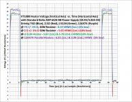
As Keit pointed out, by confusing RMS with average, my claims for the relevant heater voltages used by the Orange VT1000 Valve Tester were incorrect. Keit and I have tried unsuccessfully for the past month to get that erroneous information removed from the forum to avoid further dissemination. This post is an attempt to correct as well as expand on how the VT1000 really does drive the heaters in the tubes being tested.
The following “Heater Voltages” Microsoft Excel “XY (Scatter)” chart shows the periodic heater voltage waveforms measured for various heaters/simulators after the 5 second heater “soft start/warmup” phase. Excel formulas were used over the period of the waveform to calculate the RMS values shown.
The following “Heater Currents” chart shows measured heater voltage and current waveforms acquired during the 5 second “soft start/warmup phase” (I * V = ~114 Watts Peak) as well as at the end of the test sequence (Final I * Final V = ~68 Watts Peak) with a JJ EL34 tube. It also shows that the unit’s external laptop-type switching power supply output (“PS without I sense”) isn’t causing the voltage drops during the high current draws. “Without I Sense” shows the heater voltage waveform when the current sense resistor is bypassed (for better correlation with the previous chart).
The VT1000’s “Matching Value” for that tube was “7” (Vg = ~-15.5 V for 18.7 mA Ic) with the current sense resistor and “8” (Vg = ~-16.5 V for 18.7 mA Ic) without it. When powered by a DC power source, the “Matching Value” remained at “8” between 6.6 VDC @ 1.56 ADC and 5 VDC @ 1.19 ADC. (Regulating the heater voltage clearly wasn’t necessary for this tube). The “Matching Value” dropped to “1” (Vg = ~-9 V for 18.7 mA Ic) at 3.08 VDC @ 1.04 ADC.
Attachments

Orange VT1000 Valve Tester Heater Voltages
So after spending an hour going through this fascinating thread it all ends up as a famous qoute from Roseanne Rosseanadana!!
Check your measurements. Check them again. Get them out there for others to verify...quickly.
Stop thinking your credentials will cover your ***!
So after spending an hour going through this fascinating thread it all ends up as a famous qoute from Roseanne Rosseanadana!!
Check your measurements. Check them again. Get them out there for others to verify...quickly.
Stop thinking your credentials will cover your ***!
Absolutely! “Getting them out there for others to verify” could be a very useful feature provided by this forum/thread. But, the fact that it is apparently not possible to properly edit/correct information posted for such vetting likely severely impacts that potential utility.
So after spending an hour going through this fascinating thread it all ends up as a famous qoute from Roseanne Rosseanadana!!
Check your measurements. Check them again. Get them out there for others to verify...quickly.
Stop thinking your credentials will cover your ***!
- Status
- Not open for further replies.
- Home
- Amplifiers
- Tubes / Valves
- Testing emission without risk