OK, so here is my learning quest of the day. I have received my lm3886 Mono PCB and Power Supply PCB from Brian at chipamp.com After getting them assembled, I have a single question about the power supply board. Also, I have received my AS-2224 Toroid from Antek Inc. The second / third question relates to this.
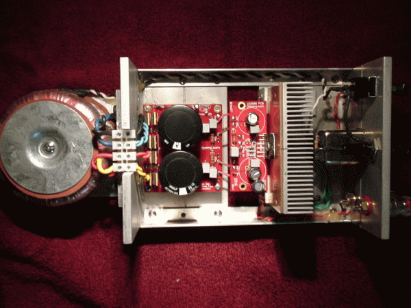
PS Board Question: The terminal posts that are mounted underneath seem to have no orientation markings. The directions are not terribly clear in this area so I will ask the obvious question: Can the outputs from the transformer go on either side? This sounds like it would not be the case and worries me that the confusion is there. I will post pictures for reference.
Toroid Question: This is my first time ever working with mains voltages, and I have been hesitant to do so. Now that I have made this leap and will be doing so, I want to be thorough before I do ANYTHING. I need to (as directed by Brians Tutorial), test VAC before the PS Board and VDC after the board. Where can I find a reliable tutorial on doing this?
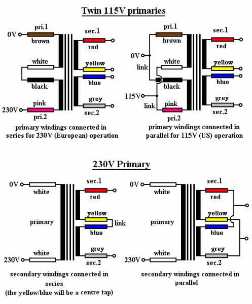
Toroid Question: There are 2 outputs (obviously), but I also see 2 sets of input wires as well as a random purple one that seems (according to the Antek datasheet) to go to the center of the transformer.. Did I buy an incorrect product?
My cloudiness in this area is making me doubtful about this project 🙁 Hate to ask for it as it goes against everything I have ever been taught, but I think I need a "Paint by numbers" approach for this part of it and learn why after I learn how.
Thanks, and if my questions are not terribly clear, forgive me.
Toroid:
Posts:
Total View:
PS Board Question: The terminal posts that are mounted underneath seem to have no orientation markings. The directions are not terribly clear in this area so I will ask the obvious question: Can the outputs from the transformer go on either side? This sounds like it would not be the case and worries me that the confusion is there. I will post pictures for reference.
Toroid Question: This is my first time ever working with mains voltages, and I have been hesitant to do so. Now that I have made this leap and will be doing so, I want to be thorough before I do ANYTHING. I need to (as directed by Brians Tutorial), test VAC before the PS Board and VDC after the board. Where can I find a reliable tutorial on doing this?
Toroid Question: There are 2 outputs (obviously), but I also see 2 sets of input wires as well as a random purple one that seems (according to the Antek datasheet) to go to the center of the transformer.. Did I buy an incorrect product?
My cloudiness in this area is making me doubtful about this project 🙁 Hate to ask for it as it goes against everything I have ever been taught, but I think I need a "Paint by numbers" approach for this part of it and learn why after I learn how.
Thanks, and if my questions are not terribly clear, forgive me.
Toroid:
An externally hosted image should be here but it was not working when we last tested it.
Posts:
An externally hosted image should be here but it was not working when we last tested it.
Total View:
An externally hosted image should be here but it was not working when we last tested it.
Last edited:
Piece of cake. I've just completed my Pass F5 and am now building the same chipamp you are. Here goes:
1. Yes; the two secondary transformer windings can go to either side. Select one of the two blue secondary wires. With an ohmmeter (DMM) determine which of the two green secondary wires is part of the same winding. Once you determine which one (the DMM should read VERY low ohms for the same winding), these go to (for example) the AC1 and AC1 (with the bar overhead) terminals. Check the other two secondary wires (the remaining blue and green) for low ohms with the DMM and connnect them to the AC2 and AC2 (with the bar overhead) terminals. For consistency (but not essential), select the blue wires to go to AC1 and AC2.
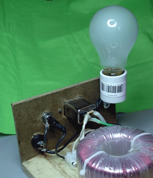
2. BEFORE you do Step One, above, wire the dual transformer primaries, fuse, power recepticle (and on/off power switch if you use one). Double check your wiring, and apply power using a lamp bulb tester in series with the transformer windings. Check the AC voltage on each of the secondaries--they should be about 22 VAC for your model. Turn off your power and disconnect from the power mains.
NOW, follow Step One, above, to connect the transformer secondaries to the diodes and filter caps as I describe. Double check your wiring. Turn on your AC power, with the lamp bulb test in series with the transformer primary windings. Without a load, on the output of the power supply you should measure about 30-31 VDC. One PS output would be positive with respect to ground; the other output should be the same voltage, but negative with respect to ground. This would conclude your PS testing.
3. You purchased the Antek transformer with the optional shield (purple wite). It's perfectly OK to use this with your chipamps--just ground the purple wire to chassis ground, and you'll be fine.
One word (or several words) of caution; you are playing with lethal voltages in the transformer primary; please be careful, and safe.
If you need more info, PM me, and I can walk you thru these steps.
If you're interested, here's my F5 build thread that I had mentioned in my last post.
http://www.diyaudio.com/forums/pass...-build-beautiful-music-different-drummer.html
http://www.diyaudio.com/forums/pass...-build-beautiful-music-different-drummer.html
That is a sexy build 🙂 So just to clarify what I understood from that. I tested the windings and I get a reading from (top to bottom in pic) the first and second wires and a reading from the third and fourth wires. On a 200ohm scale I get a 0.4 reading. The other combination (1-3 and 2-4) give me absolutely no reading. So I believe that answers the phase question. So using the second picture as reference, I will connect wire 1 (green) to top right post, wire 2 (blue) to top left post, wire 3 (green) to bottom right post, and wire 4 (blue) to bottom left post.
I will then twist the Red wires together and run them to the + post of the input jack and do the same (but opposite post) with the black wires. The Purple wire will be grounded to my chassis.
I appreciate the willingness to help 🙂
I will then twist the Red wires together and run them to the + post of the input jack and do the same (but opposite post) with the black wires. The Purple wire will be grounded to my chassis.
I appreciate the willingness to help 🙂
Cory....thanks for the phone call--I hoped that helped.
I recommend you use an IEC power connector--they make for a neat install (mount right on the chassis, and contain the fuse holder). Here's one (of many sources, to include Digi-Key, Newark, Parts Express, etc, etc):
IEC Power Jack Chassis Mount with 10A Fuse Holder
Interesting to find out both you and I got the wrong chipamp ICs from BrianGT. Makes you wonder who else might have....... Glad I found out, before I fired up my amp.....
- Status
- Not open for further replies.
- Home
- Amplifiers
- Chip Amps
- Testing and Utilising torroid on lm3886


