I have been building a MooseFET preamp for over a year. Before running things need to be set up.
I am confused about using a voltmeter. The manual states "Upon powering the unit, adjust P1 for 24.00V on the B+ rail (the power side leads of R104 or R204 make a good test point for this)."
Where do I put the negative for the voltmeter?
Also same here "Once the B+ is confirmed, with an accurate voltmeter, check the drain voltage (the drain side leads of R104 or R204 make a good test point for this. See image below). While checking the drain voltage on Q101"
I have tried it in my system and something is wrong. Sound is only just audible at full volume with no lower frequencies. Also a loud buzzing that isn't affected by volume.
Attachments
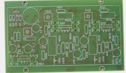
Put the negative lead on the ground terminal . Check you have put the correct component value in its proper space .
Last edited:

Post pictures when you're up and running! I've been wanting to build one of these for ages! 8)
Its stil not running. Been advised the mosphets may be dud and I have been to busy to sort out.
They don't sell these anymore due to too many problems like this.
I have since made a mosphet phono preamp (boozehound labs) and was very happy it worked first time and sounds fantastic.
I know that mosfets can have varying turn on voltages - is that the kind of problem that you're talking about? These are usually just sold as pcbs right? So you have to source the parts yourself?
These are usually just sold as pcbs right? So you have to source the parts yourself?
Yea, just bought the boards then sourced and populated myself.
Post the schematic so we know what are you talking about.
Attachments
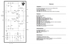
Much better schematic at DIY Audio Projects Forum.
Did you get as far as measuring for +14.8V at the point indicated?
It is possible the 4.48V-5.6V bias trim is not wide enough for "all" things sold as IRF*10. If you post the voltages you observe, we may suggest alternate bias resistors to dial it in.
Did you get as far as measuring for +14.8V at the point indicated?
It is possible the 4.48V-5.6V bias trim is not wide enough for "all" things sold as IRF*10. If you post the voltages you observe, we may suggest alternate bias resistors to dial it in.
Attachments
Much better schematic at DIY Audio Projects Forum.
Did you get as far as measuring for +14.8V at the point indicated?
It is possible the 4.48V-5.6V bias trim is not wide enough for "all" things sold as IRF*10. If you post the voltages you observe, we may suggest alternate bias resistors to dial it in.
I am sure I did, it seems so long ago I can't remember details. I do have to replace a zener diode as I thought maybe I put power cap in wrong way so changed it and instantly one of them blew. So i had put cap the correct way in the first place.
If i get the chance I will get it going the weekend to check what values I get.

- Home
- Source & Line
- Analog Line Level
- Testing a mosfet preamp help please