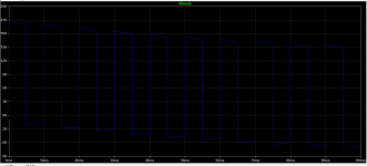
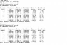
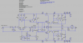
Without C7 0.000334% thd.
With it 0.000335% thd.
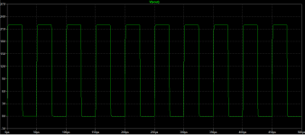
20k Hz, 44 Vpp, 2 Ohm res output.
Yes, because the C2 100uF capacitor is perfect in the simulation, and it cancel the effect. But it has series inductance in real life, and it makes the situation worse.
Sajti
Add this spice directive..
.option reltol=1e-6
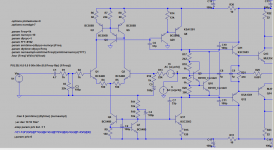
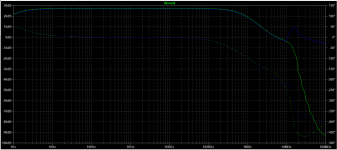
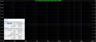
It may improve settling time but could increase sim time depending on your pc hardware specs. Not an expert but a few observation, yuo are using all high gain devices at the input stage perhaps a pair in the LTP should be enough..so you could omit or reduce some miller comp caps (comp caps at the drivers seems a little high at 100pf). Phase is good at 80° but the slope doesn't look ok at 100db. I figure you have a very high open loop gain for a CFP ops. There also appears a bump at 10mhz region. Check your open loop gain plot this could be a sign of HF overshoot, it will affect gain margin, and agree with Maestro Valery perhaps a one transistor VBE multiplier should be enough for the job.
Regards,
Albert
.option reltol=1e-6
It may improve settling time but could increase sim time depending on your pc hardware specs. Not an expert but a few observation, yuo are using all high gain devices at the input stage perhaps a pair in the LTP should be enough..so you could omit or reduce some miller comp caps (comp caps at the drivers seems a little high at 100pf). Phase is good at 80° but the slope doesn't look ok at 100db. I figure you have a very high open loop gain for a CFP ops. There also appears a bump at 10mhz region. Check your open loop gain plot this could be a sign of HF overshoot, it will affect gain margin, and agree with Maestro Valery perhaps a one transistor VBE multiplier should be enough for the job.
Regards,
Albert
So, it's been a while... I've been swapping parts and tinkering with values, but the bump doesn't want to go away.
And the slope in the OLG looks strange, I haven't simed any amplifier to look like this.
Also, while looking for the clipping point , 1% Thd, I found that it is a fine line between 0.03% at 1,35v input and 5% at 1,4v input. Is this normal?
And the slope in the OLG looks strange, I haven't simed any amplifier to look like this.
Also, while looking for the clipping point , 1% Thd, I found that it is a fine line between 0.03% at 1,35v input and 5% at 1,4v input. Is this normal?
Attachments

- Status
- Not open for further replies.
- Home
- Amplifiers
- Solid State
- test21... what next?