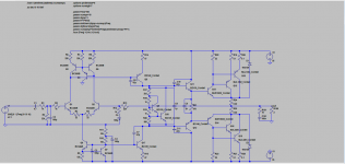
Hey guys, what to look for next?
Swapping the BD's for 1381/3503 does improve things, but I really hate how hard they are to find. 1220/2690 doesn't change things that much...
Maybe a more complex cascode or buffered VAS?
Tests were mostly done for 2 ohm res load, because I noticed some stability issues early on, so I insisted on pushing it...
Attachments
-
 test21_1.PNG40.1 KB · Views: 283
 -
 test21_10.PNG39.2 KB · Views: 113
 -
 test21_9.PNG32.3 KB · Views: 95
 -
 test21_8.PNG20.7 KB · Views: 92
 -
 test21_7.PNG20.7 KB · Views: 112
 -
 test21_6.PNG29.7 KB · Views: 105
 -
 test21_5.PNG20.5 KB · Views: 297
 -
 test21_4.PNG21.4 KB · Views: 247
 -
 test21_3.PNG32.8 KB · Views: 258
 -
 test21_2.PNG27 KB · Views: 280
and some more...
Attachments
-
 test21_20.PNG21.8 KB · Views: 102
 -
 test21_19.PNG22.1 KB · Views: 84
 -
 test21_18.PNG31.3 KB · Views: 85
 -
 test21_17.PNG19.7 KB · Views: 100
 -
 test21_16.PNG41.6 KB · Views: 97
 -
 test21_15.PNG30.6 KB · Views: 89
 -
 test21_14.PNG19.7 KB · Views: 88
 -
 test21_13.PNG40.9 KB · Views: 94
 -
 test21_12.PNG30.9 KB · Views: 90
 -
 test21_11.PNG20.4 KB · Views: 131
Phase margin and closed loop gain? CFP output stage is very tricky to simulate, it has to be tested in real hardware to verify that it will not self-oscillate.
“Alice: Would you tell me, please, which way I ought to go from here?
The Cheshire Cat: That depends a good deal on where you want to get to.
Alice: I don't much care where.
The Cheshire Cat: Then it doesn't much matter which way you go.
Alice: ...So long as I get somewhere.
The Cheshire Cat: Oh, you're sure to do that, if only you walk long enough.”
The question to muresan_c_dan - "Where do you want to get to?" 🙂
What are you trying to achieve?
Cheers,
Valery
If you are having problems finding VAS transistors like the C3503/A1381, note that they are originally CRT video drivers and it isn't always desirable to have the ultra-low Cob of that pair.
There are are still plenty of other types to use, from NOS suppliers like ELECMENTS13 (Bulgaria) for example. You can even buy new parts from the major European distributors in a large SOT223 SMD format, if that's your preference. eg BF720,721
There are are still plenty of other types to use, from NOS suppliers like ELECMENTS13 (Bulgaria) for example. You can even buy new parts from the major European distributors in a large SOT223 SMD format, if that's your preference. eg BF720,721
Hey guys, what to look for next?
Swapping the BD's for 1381/3503 does improve things, but I really hate how hard they are to find.
I don't really understand. Mouser have thousand in stock....
Sajti
“Alice: Would you tell me, please, which way I ought to go from here?
The Cheshire Cat: That depends a good deal on where you want to get to.
Alice: I don't much care where.
The Cheshire Cat: Then it doesn't much matter which way you go.
Alice: ...So long as I get somewhere.
The Cheshire Cat: Oh, you're sure to do that, if only you walk long enough.”
The question to muresan_c_dan - "Where do you want to get to?" 🙂
What are you trying to achieve?
Cheers,
Valery
Well, that cat shore was wise. A Yoda of the rabbit hole.
I want to get to understand a few things about circuit design. And what better place to look for knowledge? I followed your work, and Pete's on the slewmasters (I even built a few nice things), but without getting involved, I feel I'm going nowhere by my lonesome. I learned a hole lot about PCB design, soldering, parts selection just by reading this forum.
Now I want to find out what it takes to design, test and build something.
Phase margin and closed loop gain? CFP output stage is very tricky to simulate, it has to be tested in real hardware to verify that it will not self-oscillate.
I get an error when looking for phase margin, don't why...
I'll be back with results.
Maybe I need a new directive.
I don't really understand. Mouser have thousand in stock....
Sajti
True, but I really don't feel like going through a few hundred of those, to get to a few pairs of matched ones. So the parts that I want to use, should be easily attainable and in plenty quantity. And they also need to there job, as well as possible, of course.
Never ending story of optimum compromise...
Hmm... You don't need to match them, once one of them is ccs, and the other is the VAS.
Sajti
Well, that cat shore was wise. A Yoda of the rabbit hole.
I want to get to understand a few things about circuit design. And what better place to look for knowledge? I followed your work, and Pete's on the slewmasters (I even built a few nice things), but without getting involved, I feel I'm going nowhere by my lonesome. I learned a hole lot about PCB design, soldering, parts selection just by reading this forum.
Now I want to find out what it takes to design, test and build something.
OK, cool 🙂 Let me know if I can help with something.
A few thoughts right away:
- 1381/3503 is an excellent pair (initially designed for video applications) - not suitable for high-current circuits, but excellent for the VAS and pre-driver kind of stages. You don't have to match them precisely - in most cases, 50% hFE difference is fine. Look at it from the following point of view - in the working, self-balanced circuit, collector currents of the complementary pair will be equal. Having some h21 difference within this pair, you will have the base current difference, accordingly. So what? In CCS'ed VAS like yours, it's no problem, in the pre-driver stage - those bases are virtually connected via a low-impedance bias spreader, so no real issue as well.
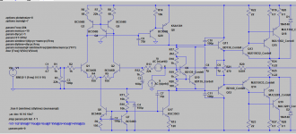
- Input stage degeneration - R4, R5 - a good practical value I would use is 100R, especially having your LTP loaded with the current mirror (overall gain of IPS is high enough). Higher local linearity and better transient response.
Those values may be lower than that, or even zero, with jFETs in LTP though, because of their lower transconductance.
- You may want to try an emitter follower in front of your VAS (Q8) - use the same BC556B as the ones you use in the current mirror.
- Bias spreader may be simpler - a single transistor, as having your OPS arranged as CFP, you need to track the temperature of the drivers only. Dual-transistor arrangement, as yours, is very good in EF arrangements, where you track both the drivers, placed on a local heatsink, and the outputs, placed on the main heatsink.
Cheers,
Valery
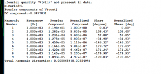
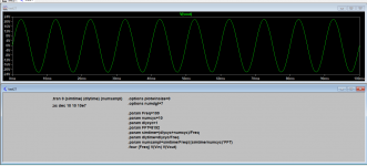
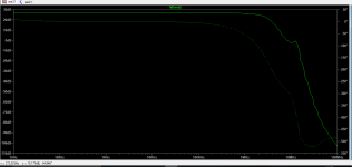
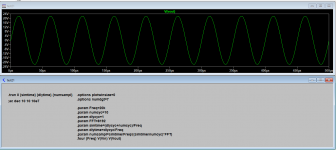
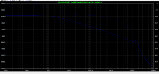
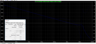
Here is the phase plot.
What do I look for?
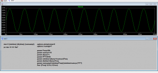
Put a cursor on the graph (click on the top equation to invoke) drag it to reach 0db reference, read the corresponding phase deg in the window, subtract with -180° the resulting difference is your phase margin.
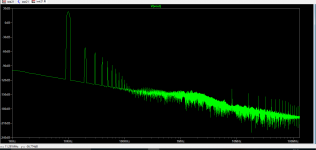
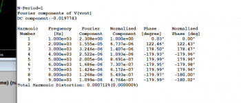
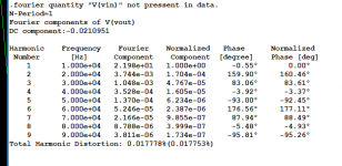
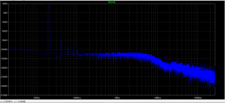
1381/3503 in vas does reduce thd quite a lot. I was under the false impression that they need to be matched.
Lowering the degeneration resistors increases thd. Even the slightest change of R9 value leads to stability problems.
I will try to ad that extra transistor to Q8.
Would you guys help me start a checklist?
What would be the things to check for in ltspice, in order, and maybe some values for margins?
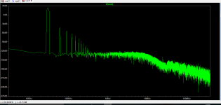
I think that there must be a conspiracy promoted by transistor companies to sell large quantities of actives with the promise that more actives gives better lower distortion results. I realize that this is a power amp, and what I am showing below is what you could use to drive an output stage, but I think, paired with a well designed neutral output stage, it could be very very good, and it would be cleaner and have less hash/grass/fuzz on the FFT with just maybe H2/H3/H4 peaks only.
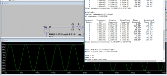
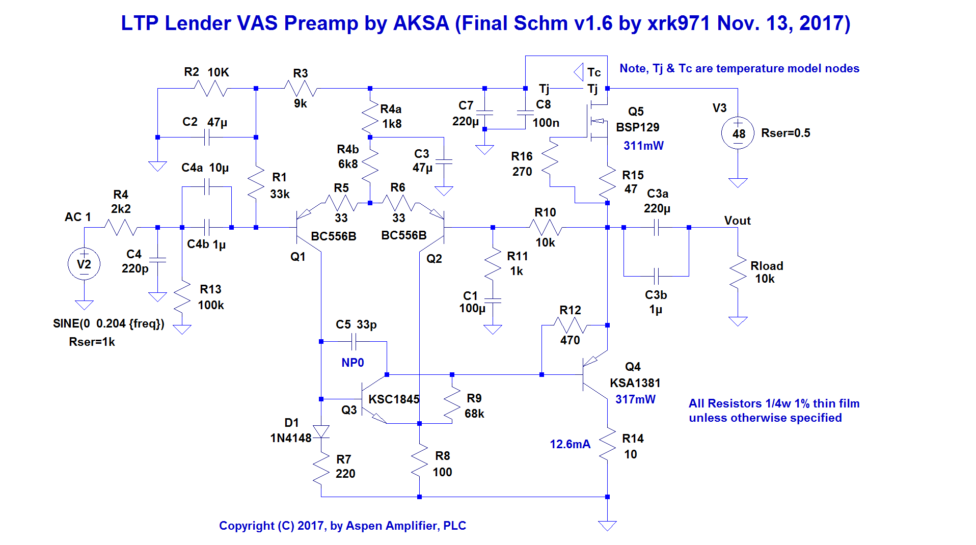
Here is a 5 transistor design by Hugh Dean that can drive 40v p-p cleanly:
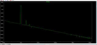
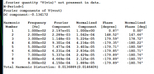
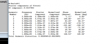
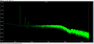
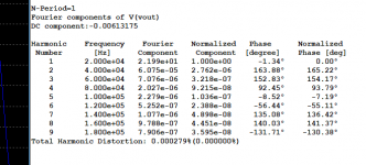
Predicted FFT for 20vpp into 10kohms:

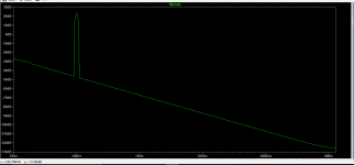
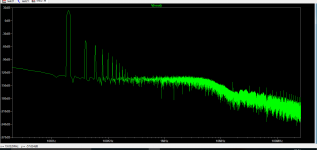
Measured FFT 20vpp into 3.4kohm load:
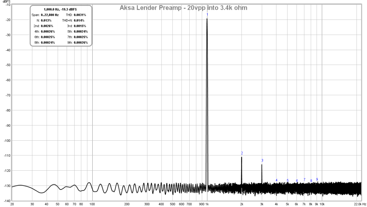
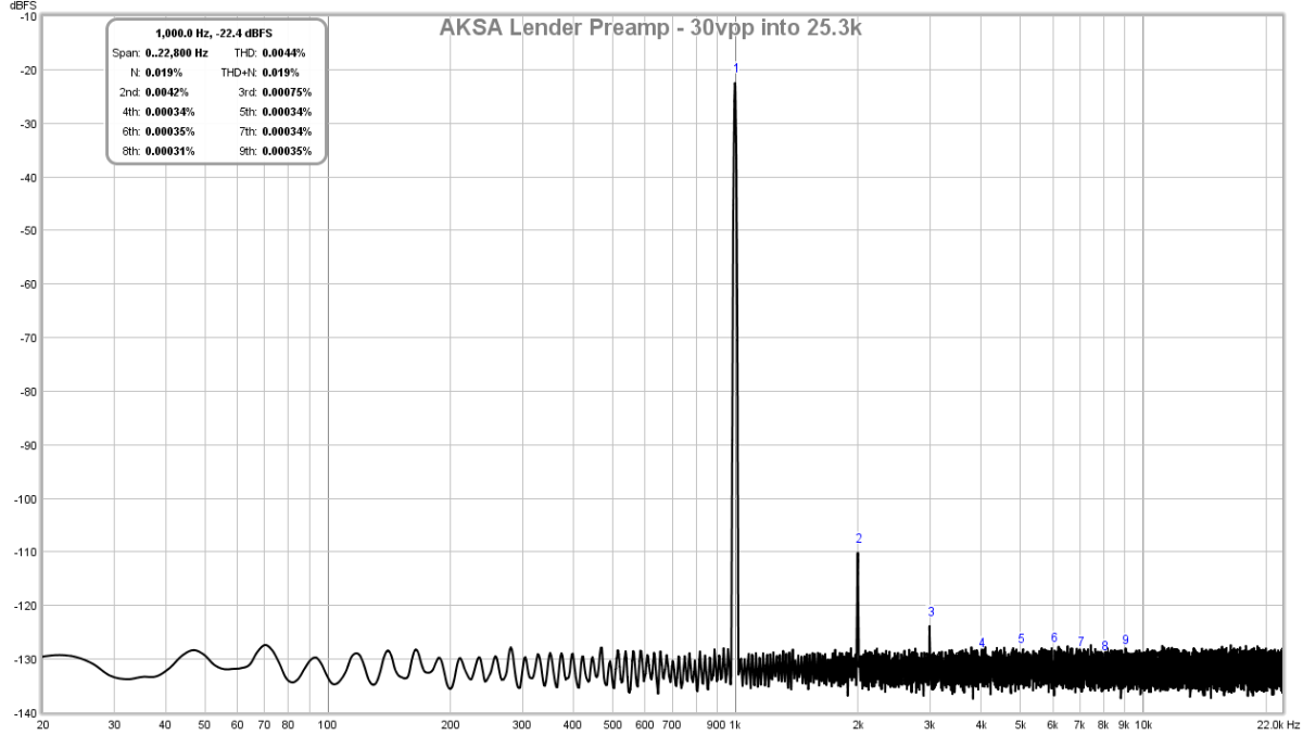
If you increase impedance of load to 25k we can drive at 36vpp and still GT this:
More info on this preamp here:
AKSA's Lender Preamp with 40Vpp Output
Btw, the 1381and 3503 are readily available as KSC3503 and KSA1381.
Here is a 5 transistor design by Hugh Dean that can drive 40v p-p cleanly:
Predicted FFT for 20vpp into 10kohms:
Measured FFT 20vpp into 3.4kohm load:
If you increase impedance of load to 25k we can drive at 36vpp and still GT this:
More info on this preamp here:
AKSA's Lender Preamp with 40Vpp Output
Btw, the 1381and 3503 are readily available as KSC3503 and KSA1381.
Last edited:
Somehow my brain must be hardwired to understand things like this. Looking for nice symmetric signal lines, i mistakenly thought i need full symmetry in topology and parts used.
This being almost blameless, why not vas to?
This being almost blameless, why not vas to?
This is inspired by Borbely-Lender VAS, asymmetric by nature but that's why it works to promote the beautiful harmonic distortion profile.
- Status
- Not open for further replies.
- Home
- Amplifiers
- Solid State
- test21... what next?