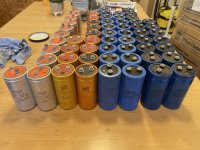
I am Building a Pass Labs Aleph 5 clone and I bought some used capacitors for the PSU from local ads.
They are 2200uF to 5800uF, with voltage rating ranging from 100V to 400V. I know I only need 63V capacitors but effort trying to get used 63V, >10000uF capacitors was futile, so I jumped onto getting these uniformly sized high voltage capacitors when these appeared on the local ads, at a very reasonable price. Beggar can’t be chooser.
I will be equipping myself with power supplies and general voltmeter and ammeter to reform these capacitors. I intend to reform them to 80% of their rated voltage and that should be more than enough for my usage.
Q1) Is there a need to reform them to 100% of the rated voltage do that they are fully “reformed”, even if I will be using them for less than 63Vdc?
But before I reform them, I would like to test if the capacitor is still good, to avoid any mishap during reform, as well as testing them after reform.
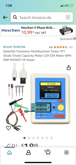
From what I gather, I need to test capacitance, ESR, leakage current of the capacitors to determine if they are still useable. I have multimeters and I am buying a DSO and a signal generator. From the YouTube video that I watched, I would need a LCR meter, ESR meter and a leakage current meter.
Q2) Please could you recommend a meter that can do all three? I do not repair electronic equipment for living, but I do attempt to repair simple household appliances, strictly hobby purpose and my budget is <USD200 for the meter(s)
Thank you!
p/s: I have training in electronic engineering 35 years ago, but only worked on system level for most part of my career, I haven’t forgotten my basics and I am fully aware of the dangers of dealing with high voltage but that is about all.
They are 2200uF to 5800uF, with voltage rating ranging from 100V to 400V. I know I only need 63V capacitors but effort trying to get used 63V, >10000uF capacitors was futile, so I jumped onto getting these uniformly sized high voltage capacitors when these appeared on the local ads, at a very reasonable price. Beggar can’t be chooser.
I will be equipping myself with power supplies and general voltmeter and ammeter to reform these capacitors. I intend to reform them to 80% of their rated voltage and that should be more than enough for my usage.
Q1) Is there a need to reform them to 100% of the rated voltage do that they are fully “reformed”, even if I will be using them for less than 63Vdc?
But before I reform them, I would like to test if the capacitor is still good, to avoid any mishap during reform, as well as testing them after reform.
From what I gather, I need to test capacitance, ESR, leakage current of the capacitors to determine if they are still useable. I have multimeters and I am buying a DSO and a signal generator. From the YouTube video that I watched, I would need a LCR meter, ESR meter and a leakage current meter.
Q2) Please could you recommend a meter that can do all three? I do not repair electronic equipment for living, but I do attempt to repair simple household appliances, strictly hobby purpose and my budget is <USD200 for the meter(s)
Thank you!
p/s: I have training in electronic engineering 35 years ago, but only worked on system level for most part of my career, I haven’t forgotten my basics and I am fully aware of the dangers of dealing with high voltage but that is about all.
Attachments


The only test I would do is to check how they sound and whether they are defective (short circuit). Only use will show whether one or two are no longer good in the long run. The volt ratings are dielectric strength ratings. For sound reasons, I would only use one type. Low capacitance loss is not relevant.
More important is: how do I put many capacitors on one circuit: head scratching work;-) And I would use plastic screws for the connections: Concretization, definition of current, thus of signal.
More important is: how do I put many capacitors on one circuit: head scratching work;-) And I would use plastic screws for the connections: Concretization, definition of current, thus of signal.
First, forget ESR. That's not an appropriate measurement for big low frequency caps. You need capacitance at 120 Hz, dissipation factor and DC leakage at the rated voltage. If cost didn't matter, and you could find a working one one, you'd get a General Radio 1617A bridge, which would do all three. It would also reform them. Lacking that, you can use any cap tester to get the value, though I don't know how well the little new ones do with dissipation factor. If you look at traditional bridges, be sure they cover the range, as many don't go high enough.
Do the DC leakage with a power supply and a current limiting resistor. Put a DVM across the limiting resistor to get the current. If you want to build something, here are some plans for a very simple bridge. https://www.conradhoffman.com/cap_bridge.pdf
Too low a value is obvious, but also be wary of caps with too high a value. That's usually the sign of chemical changes and end of life. Dissipation factors below 0.5 are probably OK for big caps. Leakage current should come down fairly quickly, a minute or so, and should probably be under a few mA, though I like to see it a lot lower.
A good cap can be reformed (what actually happens is open to debate) and the leakage current will stay low. A bad cap will reform, but every time you power it up, the leakage current will be too high, slowly coming down to an acceptable level. My experience with reforming hasn't been that great and if the current won't stay down, the cap is shot.
If you do these things you can have confidence that the caps won't be failing any time soon.
thanks for the recommendations.Peak Electronice DCA and ESR meters. Discard any with high ESR or low C.
But I’m puzzled by your claim that you couldn’t find 63V capacitors above 10,000uF. Kemet make many, and that’s just one brand.
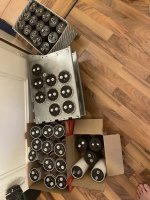
Perhaps I did not make myself clear. Due to budget constraints, I was looking for used capacitors with total capacitance of about 200mF for PSU filters, There are occasional seller with only one of this capacitance, and another with a different capacitance of another size, and the cost of postage is more than the one capacitor, you get the pictures, so when one seller have 60 capacitors of similar sizes, I jumped at it.
Last edited:
I would reform each before any testing. Limit the charging current to 10mA.
WRT testing large caps this is possibly the best: HP4282: https://amplifier.cd/Test_Equipment/Hewlett_Packard/HP_meter/HP4282A.htm Rare and limited utility but great when you have a box of caps to test. I have had good success with old caps so far. I would avoid pulls unless you know the previous use and health.
I would just charge each of them through a large series resistor and periodically check the voltage. If the voltage increases much faster than it should according to V (1 - e-t/(RC)) the capacitor under test is dried out, if it never reaches V, it is leaky. If it just charges much slower than it should, it needs to be reformed, which it automatically is during the test if you keep charging for a long time.
After that, you can discharge the capacitor under test again through the resistor and see how long it takes for the voltage to drop by a factor of e. Divide the result by the resistance and you know the capacitance.
I would choose the resistor such that the available power is not more than half a watt or so and that the time constant has a reasonable value. For example, at 200 V and 20 kohm, the short-circuit current would be 10 mA (matches rayma) and the resistor would have to have a power rating of at least 2 W, preferably 4 W to be on the safe side. The power the capacitor could dissipate if it were leaky would at most be one quarter of that, half a watt, if it happened to have a leakage resistance matching the charging resistor. Half a watt should be small enough not to overheat a big capacitor. With 20 kohm and 10 000 uF, the time constant would be 200 seconds, a suitable value for multimeter and watch measurements.
If you keep the meter connected, its internal resistance will reduce the maximum voltage somewhat. For example, with 20 kohm, 200 V and a 1 Mohm meter, to 200 V * 1 Mohm/(1 Mohm + 20 kohm) ~= 196 V.
Last edited:
thanks for the recommendations.
Perhaps I did not make myself clear. Due to budget constraints, I was looking for used capacitors with total capacitance of about 200mF for PSU filters, There are occasional seller with only one of this capacitance, and another with a different capacitance of another size, and the cost of postage is more than the one capacitor, you get the pictures, so when one seller have 60 capacitors of similar sizes, I jumped at it.
Your planning on making 200,000uF total capacitance out of 2,200uF caps? Are you using a separate enclosure just for the caps?

Just remember, if one of those caps shorts out, you have enough energy from all the rest to make a pretty good bang! I'd probably divide the thing into groups, putting a fuse between them. Be careful- you've got enough energy to do some damage. Reminds me of a photo flash unit I made many years ago, adding a big bank of HV caps to a commercial head. In hindsight, it wasn't a good idea. FWIW, I've done some experiments comparing "normal" amounts of filtering to crazy amounts of filtering and there's really no significant audible difference.
With due respect, those caps look OOOOLLLLDDDDD
In principle not trusted, by definition.
"Reforming" does not make miracles.
Please post date codes printed on them, would not be surprised at 70's vintage.
If in doubt post closeup coding pictures.
In principle not trusted, by definition.
"Reforming" does not make miracles.
Please post date codes printed on them, would not be surprised at 70's vintage.
If in doubt post closeup coding pictures.
the resistor would have to have a power rating of at least 2 W, preferably 4 W to be on the safe side.
I always use a 20W resistor for reforming, so even if the capacitor shorts, the resistor will still be ok.
There is a serious negative to too much cap. The following- A very big cap will draw a big peak current when charging both initially and on every cycle as it replenishes. As caps get bigger the charge current goes up and the time goes down meaning higher peak power. With this the AC supply, rectifiers and connections all have larger voltage drops (IR losses). The connections will also heat up a lot which causes failures. The biggest audio impact will be the EMI from the short high current charging pulses which will radiate everywhere. Putting the caps in a seperate enclosure will also bring issues of the charging pulses adding the the ground reference and providing a really hard to remove hum source.
There is an optimum where the ripple is low enough, the charging time (conduction angle) is long enough and the power supply works well enough. These are all practical real world lessons Some of us learned the hard way. . .
There is an optimum where the ripple is low enough, the charging time (conduction angle) is long enough and the power supply works well enough. These are all practical real world lessons Some of us learned the hard way. . .
Particularly with a good transformer, you might also blow up fuses if there is no soft start.
I always use a 20W resistor for reforming, so even if the capacitor shorts, the resistor will still be ok.
When you size the resistor like I recommended in post #8, its power dissipation will be 2 W when the capacitor shorts, so a 4 W resistor will be quite sufficient. Of course 20 W will be quite sufficient as well.
Thank you for the very sensible suggestion! Would a general fuse keep up with capacitor discharge or would I need special fast blown fuse?Just remember, if one of those caps shorts out, you have enough energy from all the rest to make a pretty good bang! I'd probably divide the thing into groups, putting a fuse between them. Be careful- you've got enough energy to do some damage. Reminds me of a photo flash unit I made many years ago, adding a big bank of HV caps to a commercial head. In hindsight, it wasn't a good idea. FWIW, I've done some experiments comparing "normal" amounts of filtering to crazy amounts of filtering and there's really no significant audible difference.
Perhaps I should reform them individually after they reach 50% of the rated voltage? That would save some time for reforming. The method suggested by some YouTubers takes about a day for one capacitor.
What amount of capacitance do you consider “crazy” or the general accepted level of diminishing return where the same amount of money is better off investing elsewhere to improve the quality the sound?
Last edited:
Thank you for the advice.More important is: how do I put many capacitors on one circuit: head scratching work;-) And I would use plastic screws for the connections: Concretization, definition of current, thus of signal.
Please may I ask you to elaborate “how do I put many capacitors on one circuit” and “use plastic screws for the connections”?
Thank you very much Conrad for taking your valuable time to answer my query.First, forget ESR. That's not an appropriate measurement for big low frequency caps. You need capacitance at 120 Hz, dissipation factor and DC leakage at the rated voltage. If cost didn't matter, and you could find a working one one, you'd get a General Radio 1617A bridge, which would do all three. It would also reform them. Lacking that, you can use any cap tester to get the value, though I don't know how well the little new ones do with dissipation factor. If you look at traditional bridges, be sure they cover the range, as many don't go high enough.
Do the DC leakage with a power supply and a current limiting resistor. Put a DVM across the limiting resistor to get the current. If you want to build something, here are some plans for a very simple bridge. https://www.conradhoffman.com/cap_bridge.pdf
Too low a value is obvious, but also be wary of caps with too high a value. That's usually the sign of chemical changes and end of life. Dissipation factors below 0.5 are probably OK for big caps. Leakage current should come down fairly quickly, a minute or so, and should probably be under a few mA, though I like to see it a lot lower.
A good cap can be reformed (what actually happens is open to debate) and the leakage current will stay low. A bad cap will reform, but every time you power it up, the leakage current will be too high, slowly coming down to an acceptable level. My experience with reforming hasn't been that great and if the current won't stay down, the cap is shot.
If you do these things you can have confidence that the caps won't be failing any time soon.
Cost matters, that is why I bought used capacitors, but a search on eBay showed up several General Radio 1650A, which I presumed is similar to the 1617A that you recommended, price seems affordable at around USD200~300 after adding postage to Austria where I am, the only thing that I am uncertain is where they are still fully functional.
You have provided a lot of good information in this and your other replies and I will have to print them out and keep it on my workbench to remind myself when I reform those capacitors.
Have a good weekend!
Thank you for the encouragement! Unfortunately as you rightly stated, the HP meter is rare, nothing showed up with my search.WRT testing large caps this is possibly the best: HP4282: https://amplifier.cd/Test_Equipment/Hewlett_Packard/HP_meter/HP4282A.htm Rare and limited utility but great when you have a box of caps to test. I have had good success with old caps so far. I would avoid pulls unless you know the previous use and health.
- Home
- Design & Build
- Equipment & Tools
- Test equipment for large electrolytic capacitors