Why don't you use Sockets for the chip? Much easier.!
Why don't you use Sockets for the chip? Much easier then cutting legs off.. Barbaric..Sorry but that's my feelings about such ways of fixing something.
Cutting legs of is only for devices which are Toats or DEAD, and sure not for something which is unsure.. But I know that's the point where the electronic Ghost's part ways..
Regards Chris
I did it at least three times and at least once on a later occasion.
I checked all the voltages. Every thing is just right.
I do the same unless I have access to a nice pro desolder station. Even then it is often easier
Why don't you use Sockets for the chip? Much easier then cutting legs off.. Barbaric..Sorry but that's my feelings about such ways of fixing something.
Cutting legs of is only for devices which are Toats or DEAD, and sure not for something which is unsure.. But I know that's the point where the electronic Ghost's part ways..
Regards Chris
I read of others that use the circuit as is and prefered it.The data sheet circuit unfortunately is not complete enough to make a successful amp, its more a test circuit.
anyway, i would like to learn a few things from the exercise so I am starting from the beginning and will make improvements as needed on my own.
do you believe that will solve my issues or just a suggested improvement?Try adding a small inductor in series to the speaker
also add a Zobel network directly across the output of the chip to ground.
That I did not do. what do you mean by power supply? you mean the transformer ground (center tap)? I connected it to the incoming ground at the amplifier power pins (as star ground), which comes across from the center tap.Also be sure to return the speaker ground wire back to the power supply to avoid any possibility of feedback due to your layout.
I had assumed as much. As said I want to start from the reference and work my way up. And this will balance the input bias? I already thought about doing it that way but did not know that was ideal.The input arrangement isn't great either. Ideally the wiper of the pot should be AC coupled to the input pin and the input pin connected to ground via a 20k resistor (to equal the feedback resistor value).
Why don't you use Sockets for the chip?
Because I don't have one. In fact I have never seen a socket for this pin layout. And besides sockets always seem to me crude or show a lack of faith/adventure/commitment. The real hesitation is that I only have one extra chip at the moment 😱
Funny thing is, it actually worked better before I fixed all the errors! which is of course ironic...
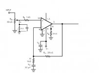
Something like this:Reading your diagnostics, it appears a tendency to oscillate depending on the position of the wiper.
As noted above, use a series R between wiper and input of say 1k, (that's Rb) and a small cap, like 1nF from that 1k to ground, on the input side.
You may need to have another 1k stopper between the top of that cap and the actual chip input pin.
And the DC path to ground of 20k of course.
Jan
Attachments
I read of others that use the circuit as is and prefered it.
anyway, i would like to learn a few things from the exercise so I am starting from the beginning and will make improvements as needed on my own.
do you believe that will solve my issues or just a suggested improvement?
The circuit 'as is' will be very dependent on the exact way it is built and also the load it is used with.
Not having an output inductor means that a 'real' load consisting of speaker cable and speaker rather than an 8 ohm resistor test load could cause stability issues.
That I did not do. what do you mean by power supply? you mean the transformer ground (center tap)? I connected it to the incoming ground at the amplifier power pins (as star ground), which comes across from the center tap.
Returning the speaker to the power supply removes any possible interaction of the speaker current with the circuitry around the chip.
It is very easy to cause stability problems unless you fully understand all the aspects of what can happen so this is an easy way to remove that possibility.
The circuit you have posted above still isn't correct around the input stage. Yours will alter the DC offset as the pot is turned. You must AC couple the wiper. Also the little cap should be on the other end of the 1k. The exact values aren't so critical, the way it all connects up is.
Copy the one I posted a little earlier 🙂
You should start with a tried and tested design and layout and work backwards from that if you wish, not the other way around.
You should start with a tried and tested design and layout and work backwards from that if you wish, not the other way around.
Where is the fun in that
😀
Without a shock or two and exploding components where is the fun ?
I did my electronics City and Guilds in 1980 on a Government funded course.
There were 12 of us on the course.
We all had to build up a power amplifier.
The fun part came at first turn on.
Exploding electrolytics the wrong way around and burning smells.
Great fun.
Every time a cap exploded there was a big cheer from the class.
To test the amps we were supplied with one record deck and one vinyl record which was Queens "Bohemian Rhapsody"
Never in my life have I so quickly come to hate a song !
I have decided the best way forward and simplest way is to just build a second board with my remaining chip. That way, hopefully, I learn something in the process. It will be slightly different, particularly in the input section, taking advantage of what I have been suggested here.
I will update in a few days when I get to the result....
I will update in a few days when I get to the result....
Not only the input, the output Zobel is FUNDAMENTAL.
Same with grounding,
Quote:
Proper way is to build a power supply on its own, connect transformer center tap straight to filter capacitor joint, which is the real ground node, and return chipamp/speaker return/etc grounds there using separate wires, that is a true star ground.
Same with grounding,
Quote:
Also be sure to return the speaker ground wire back to the power supply to avoid any possibility of feedback due to your layout.
That´s the worst way to do it, since "everything", including speaker return, connects to the real ground through the same wire.That I did not do. what do you mean by power supply? you mean the transformer ground (center tap)? I connected it to the incoming ground at the amplifier power pins (as star ground), which comes across from the center tap.
Proper way is to build a power supply on its own, connect transformer center tap straight to filter capacitor joint, which is the real ground node, and return chipamp/speaker return/etc grounds there using separate wires, that is a true star ground.
Proper way is to build a power supply on its own, connect transformer center tap straight to filter capacitor joint, which is the real ground node, and return chipamp/speaker return/etc grounds there using separate wires, that is a true star ground.
The power supply is on a separate board. The center tap goes to the amp board to a star ground with separate wires for each ground path.
Which includes the center of the smaller filter caps as close to the power pins (as suggested by the datasheet and every other application I have read.
If that is not the established DIY methodology then I will apply the suggestion to move the caps away from the amp to the first ground point star.
I accept the tip, but fail to see how that could cause the problem I experience at mid volume.
also a side question: Is it possible/recommended to made this chip amp DC stable? I would be interested in this possibility. but for the current purpose of a test and measurement amp it is unwanted.
- Home
- Amplifiers
- Solid State
- Test amp