Please do not call these simple inductors "tesla-coils" - that is absolute nonsense and causes eye cancer.

I think they just function like a common mode choke for signals above the audio band. Below that they would have little or no effect, depending on the cut-off Hz.ok, but how does this solution differ from using an input transformer?
Yes, of course,Please do not call these simple inductors "tesla-coils" - that is absolute nonsense and causes eye cancer.
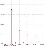
in the absence of inductive coils, the transient characteristics have deteriorated, after bringing them back to normal, we get this..., with such a spectrum of distortion, the sound turns out to be like an ordinary "transistor sound"....
Attachments
It is a transistor amplifier producing transistor sound, what else?
No coil of any kind will change that.
No coil of any kind will change that.
Y
Not even a coil since inductance is cancelled.
You are negating those separate emitter resistors.
In a nutshell: they do nothing good, and damage proper circuit operation.
What's the point?
You are just shorting emitters together with a piece of wire.Hey guys. Interesting topic title.
About 8 or 9 years ago I already built an amplifier using inductance for compensation. Moreover, inductance is really used in audio amplifiers in input circuits. But there are some conditions for their use - for transistors this is a cascode circuit and the rating of this inductor I used is no more than 100 μH, and naturally it comes with a core. Making such an inductance without a core is certainly an attractive idea, but calling it a Tesla coil somehow never occurred to me, hmm...
The implementation of inductive compensation in the input circuit is very similar, to improve linearity, and the use of bidirectional winding means that this compensation is grounded to the GND from a low-resistance point. Not the best solution, but impressed by the no-compromise solution))).
Not even a coil since inductance is cancelled.
You are negating those separate emitter resistors.
In a nutshell: they do nothing good, and damage proper circuit operation.
What's the point?
I haven't a clue what is meant by "the use of bidirectional winding means that this compensation is grounded to the GND from a low-resistance point", but having an inductor across input stage emitter degeneration resistors has the advantage that you can combine the noise and DC offset performance you would have without emitter degeneration with the slew rate you get with emitter degeneration. A potential disadvantage is hum pick-up, if you use the wrong type of inductor.
In my design, this L/R compensation circuit was necessary to increase the gain of the input stage while maintaining linearity in the audio frequency band.A potential disadvantage is hum pick-up, if you use the wrong type of inductor.
Now I have already converted the model to linear amplification without a compensation coil, but it is no longer possible to obtain the same characteristics in the model as when using this coil.
Similarly, the spectrum of harmonics - without a compensation coil turns out to be approximately the same if the output stage is transferred to class A at least up to 4 W of power; for higher power after 4 W it goes to class AB.
P.S. In general, the topic convinced me that there is no need to make a compensation coil.)))
agreed. Another elephant in the room is LTSpice assuming the inductance being constant over frequency - which in this case is far from reality.
Off topic: I was once simulating a power electronics circuit with a 300 μΩ current sensing SMD resistor using LTSpice. I realized, of course, that the slightest series inductance could cause a big difference in behaviour because the L/R time constant would already be 3.3333... μs with only 1 nH of inductance. So I added a 1 nH series inductance and an RC filter to compensate for its effect, and all of a sudden all currents were about four times smaller. In the end, it turned out that unlike any other simulator I ever worked with, by default, LTSpice adds a 1 mΩ series resistance to any inductance you place - more than three times the value of the current sensing resistor.
- Home
- Amplifiers
- Solid State
- Tesla Coil in amplifier