Hi
I have bought a Tent XOClock that I plan to install in my vintage Micromega Stage 2.
It seems that the clock circuit is a little different from the one depicted at tentlabs online installation guide, (http://www.tentlabs.com/Products/cdupgrade/xo2xo3/assets/XO23mounting.pdf ) so it got me wondering how to install it.
I've found a guide for the LCclock though: IstruzClockE-P
Question is can the Tentclock be installed in the same way as the LCclock or is there different (and/or better) way?
Thanks
I think in general the answer is yes. The '04 seems to be used to generate the clock signal. The LC instructions shows how to disable it and inject the clock signal.
Should be the same for the tent clock. If there is a better way depends on how the clock distribution of the stage2 is done. There might well be a better way, but that would be too much modding for the default LC/tent customer.
And you need the service manual to figure it out (or knowledge and some time to reverse engineer).
Thanks for the answer!
Now I have a problem number 2: The Stage 2 PCB on the photos in the link is different from mine! Anybody know anything about different versions, revisions? Can I still use the procedure in the link above?
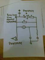
My PCB has part number 161193/5 and next line says "14-94".
These are the changes visible in the photos:
-I have a 74AC04PC instead of the 74HCU04 in the link (but the datasheet looks similar)
-The transistor next to the crystal is missing on mine (could that be just a muting transistor for the digital out, ie unrelated to clock mod?)
-There is also a resistor along the 74HCU04 paralell to the edge of the pcb, which I don't have.
I'm trying to reverse-engineer the PCB before I start soldering and cutting but it is a slow process to me and the clock area looks different than other players. Thankful for any help!
Now I have a problem number 2: The Stage 2 PCB on the photos in the link is different from mine! Anybody know anything about different versions, revisions? Can I still use the procedure in the link above?
My PCB has part number 161193/5 and next line says "14-94".
These are the changes visible in the photos:
-I have a 74AC04PC instead of the 74HCU04 in the link (but the datasheet looks similar)
-The transistor next to the crystal is missing on mine (could that be just a muting transistor for the digital out, ie unrelated to clock mod?)
-There is also a resistor along the 74HCU04 paralell to the edge of the pcb, which I don't have.
I'm trying to reverse-engineer the PCB before I start soldering and cutting but it is a slow process to me and the clock area looks different than other players. Thankful for any help!
Thanks Mooly!
I've already modified it with new opamps as per Your recommendation, and it was a definitive improvement. I listened through my old familiar recordings and clearly heard some differences:
-much more definition in the bass, absolutely no problem (depending on the quality of the mix) to separate bass drums, bass guitar and synth bass.
-slightly richer, warmer overall sound, but minute difference
-I can hear cymbals "forever"
-I also hear hiss in the mix where analogue tracks are faded in and out during a song. Didn't hear that before, and it got me a little surprised as to how much better the treble resolution was. But absolutely not intrusive.
Overall: Worth the money and work to the extent where I can only recommend everyone who hasn't done it to change opamps.
(if you read this and want the specs just search for my thread)
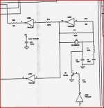
Regarding the schematics: It is also the same version as in the online clock-upgrade manual, so not hte same one I have. Different IC as described above, and it seems (though a little hard to read) different pinout from the 74ac04pc.
Is it correct that the right side of the crystal goes through R10 and then to pin 1 on the 74hcu04? Pin 1 on my 74ac04pc is ground or common (as well as 3-5-7).
I'll try to post a schematic of the clock in my PCB. If modding is no good I'll not pursue it.
I've already modified it with new opamps as per Your recommendation, and it was a definitive improvement. I listened through my old familiar recordings and clearly heard some differences:
-much more definition in the bass, absolutely no problem (depending on the quality of the mix) to separate bass drums, bass guitar and synth bass.
-slightly richer, warmer overall sound, but minute difference
-I can hear cymbals "forever"
-I also hear hiss in the mix where analogue tracks are faded in and out during a song. Didn't hear that before, and it got me a little surprised as to how much better the treble resolution was. But absolutely not intrusive.
Overall: Worth the money and work to the extent where I can only recommend everyone who hasn't done it to change opamps.
(if you read this and want the specs just search for my thread)
Regarding the schematics: It is also the same version as in the online clock-upgrade manual, so not hte same one I have. Different IC as described above, and it seems (though a little hard to read) different pinout from the 74ac04pc.
Is it correct that the right side of the crystal goes through R10 and then to pin 1 on the 74hcu04? Pin 1 on my 74ac04pc is ground or common (as well as 3-5-7).
I'll try to post a schematic of the clock in my PCB. If modding is no good I'll not pursue it.
The 7404 is just used as an invertor/buffer, don't worry about different letters on it.
I've never altered the clock in mine so this is just a general comment if I were figuring it out myself.
The output of the oscillator is pin 10. So pin 10 has to be the new injection point of any new oscillator. The easiest way to do this is to carefully snip pin 10 on the IC to isolate it. Be careful and do it so you can always reconnect if needs be. The print on these isn't DIY friendly for unsoldering components.
Conect the new osc to pin 10 print on the PCB
Looking at both circuits above I would remove the crystal and the feedback resistor (the 100k R1 in my circuit).
Your circuit shows a cap from pin 10 to ground. Is there one ? seems odd to me. I would remove it if so as it was for the inbuilt osc only.
My circuit has a transistor to kill the osc (mute) yours doesn't.
If it doesn't I would tie pin 11 to ground to disable that invertor.
If it does ? and I can't say what effect of doing away with the mute would be, remove the transistor and tie pin 11 as above.
You could always use the mute to kill the new osc but I would need one in front of me to play with.
- Status
- Not open for further replies.
- Home
- Source & Line
- Digital Source
- Tent XOClock in Micromega Stage 2 - how to