10x the price: Are these a fire hazard, too? LOL
"The Airpax® 6700 series is a RoHS compliant, positive snap action, single pole / single throw, a subminiature bimetallic thermostat that provides accurate and reliable sensing and switching in a single device. The 6700 series thermostat dimensionally conforms to the international product package standard Y220 / TO220.
Thus, the 6700 may be automatically placed and soldered onto PC boards with high speed automated equipment, eliminating the need for the expensive hand placement and termination required today for most power supply thermostats."
https://www.sensata.com/products/temperature/6700-series-220-subminiature-thermostat
https://www.sensata.com/sites/defau...iature-bimetal-disc-thermostats-datasheet.pdf
Last edited:

I have TIP31 and KSD-01F, try to cut the black package material, I can cut through KSD-01F quite easily without any sound but not TIP31, it's much harder you can hear scratching sound. So KSD-01F material is just plastic. For burning test I'll put them stainless steel plate over open gas stove. The plastic does not melt, and switch is opened, close again after cooling down (with water from tap). The packing material can not be so rigid due to the metal expansion I think that is why it's high temp. plastic, nylon (360 deg C). Mine is direct from KSD factory, one on Taobao maybe having fake packing although the metal maybe real.All this horses*it about them catching fire... if @Koonw has a bunch of them perhaps he can hit one with a blow torch and see what it does...
Last edited:
Aside from what method turns on the fan... I was thinking what's the best way to determine what temperature to set, rather than just pulling a random number out of my butt. So I was thinking one should build their amp and install an exhaust fan somewhere, usually in the back near the IEC jack. Then once the amp works, run it for 4 or 5 hours at room temperature until it totally warms up. Then with a laser thermometer take temperature readings across the chassis, average them. Now add 10-15 degrees to that number. That is your set point for when the fan should kick on. You dont want your fan running when when the amp is running fine, but you do want some cooling if it should go above 10-15 degrees above where it normally runs. Now buy a sensor for that temp and install your sensor switch be it a bi-metal, or relay circuit, etc. Then contact install the sensor to the chassis at a place where you measured the temp near the average or lower. Not near a tube but somewhere where the chassis rides at the average temp. For something like this I see no way to predict what set temp you need until you have a working amp and measured where it likes to operate at normal room temp. If it's summer and you're not running the A/C then temps will rise but if it reaches that 10-15 degrees above normal, the exhaust fan will kick in.
Last edited:
And please no WILD guesses and assumptions, we are talking switching a PC supply type Fan, so 12V and a couple hundred mA tops 😱
Expected temperatures way below 100C or simply the whole project would not make sense (boiling electrolytic fluid anybody? 😉 )
Expected temperatures way below 100C or simply the whole project would not make sense (boiling electrolytic fluid anybody? 😉 )
I would use a 3" or 4" panel fan, mains powered.
The DC fans are actually AC fans with a conversion circuit inside, and those are less reliable than AC fans.
The circuit changes DC to AC, the rotor is a solid squirrel cage type, the winding is fixed, no brushes or slip rings.
After the circuit, the build is like an AC fan.
Just put one in parallel with mains supply, as far away from the tubes as you feel will not give thermal shock.
Tubes run hot, so an always on fan is an advantage at times.
Flow rate can be decided by ambient temperature at OP location, Holten.
The heat thrown out by the tubes at steady state conditions, in KCal is the heat that is needed to be removed by the heat sinks / fans / combination.
Zimble....
Last edited:
If your equipment catches fire then these plastic switches are the least of your concerns. I hate to break the news to people but every dimmer switch in your home has a TO220 triac inside.
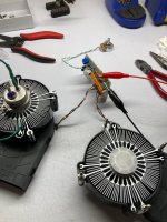
I mocked up one of these today, to test out my CPU cooler fans, and just wanted to say that this circuit can tolerate some junk bin part sub nonsense and still work. It works despite off-brand transistors (2N2222), an off-spec MOSFET (FQP3N30) without a heat sink*, an old re-formed capacitor, and a 100k pot in place of the thermistor. Two 12V fans in series run fine with a 24V feed, and if the zener runs the fans too high at baseline, you can clip it out and the circuit will still work. Alas these fans get noisy when blowing against finned heatsinks, but now I know! Thanks to Mark and this little mocked-up circuit.
*you'll probably kill your MOSFET if you run it too long un-sinked, though, mm hm. Just sayin'.
*you'll probably kill your MOSFET if you run it too long un-sinked, though, mm hm. Just sayin'.
Attachments
Now we have series caps in the new dimmers, and a selector switch.
Cheaper, more reliable, and saves energy, compared to the triacs. Less heat also.
Last triac type I got in 2019 had 7 way selector and a BT131in TO-92 package, the dimmer cost me all of 28 Rupees! (35 US cents)....
Still working, much to everybody's surprise...
Cheaper, more reliable, and saves energy, compared to the triacs. Less heat also.
Last triac type I got in 2019 had 7 way selector and a BT131in TO-92 package, the dimmer cost me all of 28 Rupees! (35 US cents)....
Still working, much to everybody's surprise...
- Home
- Amplifiers
- Tubes / Valves
- Temperature controlled fan