Hi and thank you for the forum!
I bought this equipment a week ago and it was quite OK when I did resistor, capacitor and diode measurement (user manual). anyway, it didn't go so well when you wanted to check the characteristics of a transistor.
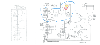
I decided to go through the calibration according to the service manual and this is where I ran into problems. I tried doing point 4 "adjust intensity range" INT RANGE potentiometer (R1245) rotated sluggishly so I sprayed it with some electric lubricant (see picture) then when I started again, the intensity knob no longer worked. I checked the service manual again and drawing 8 (see attached picture) and discovered that the resistor R1236 had browned. I changed it and then this browned again. I did ohm measurement on R1245 mounted on PCB and it varies between 0 and 1Mohm so I don't think the problem lies here. I suspect that it lies in the Z-Axis amplifier and the part that ensures that there is a constant current flow throw this operational amp. In other words, I suspect that C1236 or Q1234 are the culprits. What do you think? any advice can be of great help. It is quite difficult to pick out the whole CRT Circuit PCB and don't want to do it unless absolutely is necessary.
Another solution that I wanted to try is to isolate the board from all the remaining parts and apply power only to the yellow part of the drawing (External +30, -30VDC and 200VDC) via P1130, then inject a square wave (20Vp-p) on the anode part of CR1209 and see what the OSC have to say in the collector part of Q1226 if it looks like on the graph. What do you think? Transformer T1240 is powerless so there shouldn't be a mega-voltage out to the CRT (-3450V) right?
thanks!
I bought this equipment a week ago and it was quite OK when I did resistor, capacitor and diode measurement (user manual). anyway, it didn't go so well when you wanted to check the characteristics of a transistor.
I decided to go through the calibration according to the service manual and this is where I ran into problems. I tried doing point 4 "adjust intensity range" INT RANGE potentiometer (R1245) rotated sluggishly so I sprayed it with some electric lubricant (see picture) then when I started again, the intensity knob no longer worked. I checked the service manual again and drawing 8 (see attached picture) and discovered that the resistor R1236 had browned. I changed it and then this browned again. I did ohm measurement on R1245 mounted on PCB and it varies between 0 and 1Mohm so I don't think the problem lies here. I suspect that it lies in the Z-Axis amplifier and the part that ensures that there is a constant current flow throw this operational amp. In other words, I suspect that C1236 or Q1234 are the culprits. What do you think? any advice can be of great help. It is quite difficult to pick out the whole CRT Circuit PCB and don't want to do it unless absolutely is necessary.
Another solution that I wanted to try is to isolate the board from all the remaining parts and apply power only to the yellow part of the drawing (External +30, -30VDC and 200VDC) via P1130, then inject a square wave (20Vp-p) on the anode part of CR1209 and see what the OSC have to say in the collector part of Q1226 if it looks like on the graph. What do you think? Transformer T1240 is powerless so there shouldn't be a mega-voltage out to the CRT (-3450V) right?
thanks!
Attachments
Pulling out the transistor and checking it will be the easiest step ( first step). Please do not spray any stuff in to Tektronix curve tracers. I am not sure about 577, Tek 576 has transistors on sockets and it is easy to check.
Thank you for your reply,
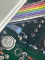
I think it is in socket (see the picture). But I don´t have any experience about this type of socket. Is only to pull out? About the lubricant is to late! I hope that what I did not affect the functionality of the scope, I spray this lubricant to all the trim-pots in the instrument, very careful of course and only to the Potentiometer. But thanks for your the advice. I will remember that!
I think it is in socket (see the picture). But I don´t have any experience about this type of socket. Is only to pull out? About the lubricant is to late! I hope that what I did not affect the functionality of the scope, I spray this lubricant to all the trim-pots in the instrument, very careful of course and only to the Potentiometer. But thanks for your the advice. I will remember that!
Attachments
Certain types of carbon amalgam can be dissolved by switch cleaners. Deoxit D5 can do this -- I've seen tracks dissolve in front of my face, where a carbon track becomes a piece of plain paxolin... If you are in any doubt, some pots can easily be dismantled, so you can see if the tracks are ok. I do not know if your lubricant has a cleaning agent...maybe it's safe for pots...or maybe it's designed for industrial applications and not delicate tracks?
The picture shows no socket but soldered connection. Servicing Tek curve tracer requires capability to de solder the components carefully if it is a suspect and test it Transistor tester. Also carefully not all connections as Tek has many wires connected using sockets. If you are not certain request a technician help to locate the fault. Since Tek tracers have high voltage points, not easy to power up and test but if you know the board has no HV , then use a multi meter to check voltages as indicated in the service manual. Better first to de-solder the pot / check outside whether it shows proper resistance before trying anything else. Are you having any experience with soldering/ de soldering electronic components?
Thank you very much for your reply, kannan_s. The two transistors, Q1234 and Q1226, were faulty. I replaced them with 2N5401 and 2N5551 and now the intensity knob working fine and I can go forward with the "Adjust intensity range" procedure. This two transistor using connection sockets and the replacement was very easy.