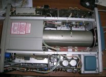
Old pieces of test equipment from brands like Tektronix, HP etc. are still used today by many people due to their really high quality. However, many times, when they are in need of repair, spare parts prove to be quite difficult to find, especially in reasonable prices. I found myself in this situation around two and a half years ago (July 2018) when my trusty Tek 475 oscilloscope presented a fault in its high voltage power supply.
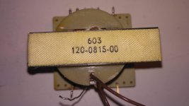
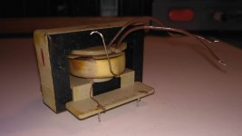
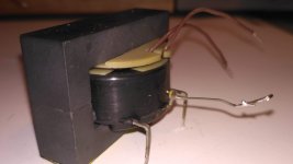
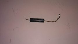
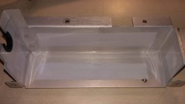
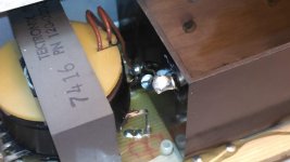
This scope has presented some other faults in the past. Its CRT was replaced in 2017, after being broken, during shipping. Also, the high voltage multiplier was replaced in June 2018. After that, a slight hissing noise could be heard, when turning the scope on (something was arcing inside the high voltage box). The noise, however, would stop after a while (5 – 10 seconds), and the scope would work normally, so I did not do anything about it. One or two weeks later, this noise became continuous and the display stopped functioning. I opened the scope and removed the vertical preamp board and the HV cover (as described in the service manual) only to find a faulty HV transformer (the secondary winding measured open between the tap providing the cathode bias and the end going to the HV multiplier to provide voltage for the post deflection anode).
From this link you can download the service manual:
475 Instruction Manual | Tektronix
The high voltage circuit schematic is on page 220.
Attachments
-
 Front.JPG606.6 KB · Views: 303
 -
 Crt and vertical output amp.JPG697.1 KB · Views: 307
 -
 Main board.JPG682.6 KB · Views: 245
 -
 Vert preamp board.JPG657.5 KB · Views: 356
 -
 Trigger board.JPG666.8 KB · Views: 284
 -
 Faulty hv transformer (2).jpg828.1 KB · Views: 279
 -
 Faulty hv transformer (1).jpg450.5 KB · Views: 248
 -
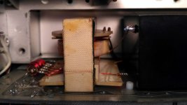 Faulty transformer inside HV compartment.jpg758.9 KB · Views: 278
 -
 secondary open.jpg672.1 KB · Views: 260
 -
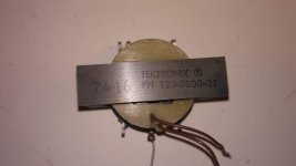
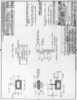
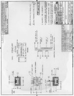 120-0815-00 x-former data.JPG120.7 KB · Views: 305
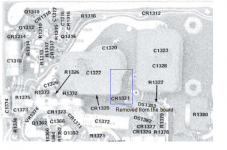
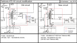
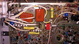
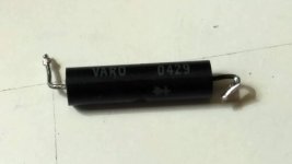
My options, not being able to find a replacement part on the internet, were, either to have the faulty transformer rewound or try and modifiy the circuit so as to use the transformer from a donor Tek 465 I had. After asking my friend and fellow diyAudio member George ( https://www.diyaudio.com/forums/members/gpapag.html ) for his opinion, we agreed that the easiest and less risky way of going was the modification. The modified circuit would use the end of the 465 transformer's secondary winding for providing both the cathode bias and the voltage for the HV multiplier (U1321). Also the doubler on the cathode supply (CR1320, 1321 and C1320, 1322) used originally in the 475 would be replaced by a half wave rectifier, as in the 465. So I removed the HV transformer (part number: 120-0800-01) and the HV diode (part number: 152-0409-00 ) from the “organ donor” 465 scope, so as to install them in my 475 scope.
Attachments
Last edited:
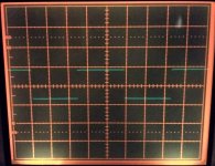
Some days later, I did the installation of the new parts in the 475 and all the changes outlined previously. The 465's transformer took the old one's place. CR1321 was removed completely from the circuit. Also the new HV diode was placed inside the hv cover and soldered to the appropriate points. Excessive care has been taken for all solder joints to be as smooth, round and without sharp edges as they could, to prevent arcing. For the same reason the inside of the hv cover was covered with 0.3mm thick PVC. Finally the scope was put all back together, plugged in and a happy green trace appeared behind the crt graticule. Measuring the CRT cathode bias with the new circuit using a X100 HV probe showed -2441V (according to the manual it should be -2450V ± 49V, so it's within spec). Also, calibration was checked (at least as far as I could check it) and some adjustments were performed (mainly display and horizontal system calibration) with some help from George. Since then, the scope has been used many times for extended periods of time and is still in full working order, proving that the repair was successful.
Attachments

You would be left with no oscilloscope had you not repaired it and that was a strong drive for you 😉
On the other hand I am not aware of many at your age who can find their way through complex schematics and proceed with successful repair and attempted full calibration on an oscilloscope as this one with no prior experience.
Kudos to you Marios.
Analog electronics is the sea of joy for some (*) and we are glad to see you young sailors here
George
(*) but try to steer away from the ‘High End’ shore 😀
