Happy New Year to all,
Please Help. I have a good old TEK 465, but now I can`t regulate the brightness.
Also, there is the return line on the test signal, do not turns off.
After a lenghty search, I saw that the signal after CR1344 (fig. 64) at J6-10, for unblanking to Z axis amp. does not match the service manual, J6-10.jpg
There is no narrow portion of the pulse (fig. 64), Page 215.jpg.
I continued and came to a point J5-2 ( fig. 63) base of transistor Q1306, Page 216.jpg. On the base Q1306 there is a good pulse (similar to Fig. 63), trace B, Q1306.jpg, but the collector's no sign of him, trace A . All elements of the voltages around the Q1306 are correct?
Perhaps the pulse missing obtained in another way, through some other part whitc I do not see
I'm spinning round in I have no idea what to ask next.
Can someone help me.
Thanks in advance
Aleksandar
YU1SAN
P.S. Sorry for the bad translation into English.
Thank you for calling.
No, it is not possible
Generally, brightness control is very small. Minimum illumination is somewhere in the middle of the potentiometer. Also, there is great change of focus from changing the position of the potentiometer for brightnes
Aleksandar
No, it is not possible
Generally, brightness control is very small. Minimum illumination is somewhere in the middle of the potentiometer. Also, there is great change of focus from changing the position of the potentiometer for brightnes
Aleksandar
The change in focus at normal viewing brightness suggests to me a high voltage problem. If you have the proper meter to measure the CRT cathode voltage, around -2500V, make sure that voltage is stable. DO NOT attempt to meausre the anode voltage, around +15,000V. Tek liked to use on old Triplett 630NA VOM on the 6,000V range to measaure cathode voltages. An unstable high voltage usually means the displayed waveforms will grow or shrink as you change the brightness.
Dear friend,
Thanks for the very quick advice and explanation
I am unable at this time to measure voltage greater than 1000V. However, by the end of the week I will find a suitable voltmeter.
Aleksandar
Thanks for the very quick advice and explanation
I am unable at this time to measure voltage greater than 1000V. However, by the end of the week I will find a suitable voltmeter.
Aleksandar
Dear Loudthud,
I'm here with the measurement results.
So, the cathode voltage does not change with a change in intensity or focus.
This voltage is -2500V.
Ug1 voltage is differs very little than the voltage at the cathode, approximately Ugk=-50V, which means that ug1 about -2550V. Then the intensity of a potentiometer to a minimum.
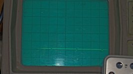
When this potentiometer to maximum, then appear negative pulses of about 100V, so it is now the minimum at about -2650V. See picture!
Voltage to focus UG3 changes from -1600V (pot min) to -2000V (pot max).
The best focus for UG3 about -1900V.
All measurements are done with Tektronis probe P6015 to 40 kV, (1000x, 3pf. 100M)
That's it.
what next?
Aleksandar
I'm here with the measurement results.
So, the cathode voltage does not change with a change in intensity or focus.
This voltage is -2500V.
Ug1 voltage is differs very little than the voltage at the cathode, approximately Ugk=-50V, which means that ug1 about -2550V. Then the intensity of a potentiometer to a minimum.
When this potentiometer to maximum, then appear negative pulses of about 100V, so it is now the minimum at about -2650V. See picture!
Voltage to focus UG3 changes from -1600V (pot min) to -2000V (pot max).
The best focus for UG3 about -1900V.
All measurements are done with Tektronis probe P6015 to 40 kV, (1000x, 3pf. 100M)
That's it.
what next?
Aleksandar
Attachments
Aleksandar,
I have a 465B. It is very similar, but not the same as the 465. In the service manual for the 465B, I do not see the pulses you are looking for.
In general I have to fall back to the general troubleshooting methods that I have learned to follow on Tek scopes.
1)Check all the power supplies. There is usually only one that is adjustable. Do not adjust it unless you have an accurate meter and intend to re-calibrate the whole scope. Also, check that the voltages are stable when the scope in malfunctioning. Sometimes it is hard to determine if the malfunction causes the power supply to go out of regulation, or if the power supply is malfunctioning and that causes the circuitry to misbehave. A fault in one power supply may cause others to also misbehave.
2)Pay extra attention to the setup that should be explained in the service manual to get the scope into the mode where it should produce the waveforms depicted in the manual. If any of the switches that change the scope mode do not function properly (such as Horizontal mode "B Intensified", "B runs after delay" or the "Alt/Chop" button) you may not see the expected waveform.
3)If the display goes out of focus, it could be that the horizontal or vertical deflection plates are not at the correct common mode voltage. this is usually a power supply or Beam Finder problem.
4)Some parts are impossible to find if you need one. If you can find a broken scope that is the same model, it will be a good source of spare parts and shouldn't cost very much.
5)If you can see the re-trace (where the beam moves from right to left) look at the output of the Z axis amplifier and the circuit called a "DC restorer" that translates the output of the Z axis amplifier to the grid of the CRT. It could also be that the CRT is just worn out after 40 years of use.
Thank you for calling and for taking your time to comment.
Now in Serbia after midnight and I will not be able to tell you exactly give all my observations.
This weekend I'll be gone and I'll get back the Sunday afternoon.
I'll try to recapitulate all my activities on repairs.
I wish you a nice weekend.
Aleksandar
By the way, I am first checked all DC voltages and they are all correct and have a small ripple.
Hi Loudthud,
Your remark that you have a 465B helped me to see better!
I've downloaded from the website service manual for 465B and read the full description for DC restorer, which I have not had in my manual for 465. And more importantly, that there are waveforms 91, 93 and the center tap of T4015 (50kHz), figures 3.10 and 3.11, pages 3.23 and 3.24.
Where I see the problem?
I do not have the appropriate waveform 93 pictures 3.10 and 3.11, diagram B. A diagrams are OK. Please refer to Figure 1 in attachment.
The changes in voltage from 15V to 95V exist like in the diagram 91, and the anode CR4112 (465B), but at the cathode voltage on CR4112 is only part of the T4105, 6Vpp (50kHz). DC level of this voltage varies from 15V to 100 with changes in the brightness, min to max.
When I change the voltage at the trim pot R4109 (CRT Bias), at point 93 of the DC level rises from 0V to 55V when the brightness on the minimum. When the brightness at maximum, Point 93 goes to 100V, and R4198 almost no influence, except very few modulation the voltage (50kHz) with voltage from point 91, see Figure 2.
I checked all the diodes and resistors of about point 93 with DMM. Everything is OK.
I do not know what I did not see
Is this perhaps the other reason why I can not make adjustments to brightness?
l no idea what to do next?
Thanks
Aleksandar
Notes:
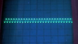
Fig.1 Point 93. The brightness is at minimum. Trim pot R4109 is changed from 0 to the maximum. DC level (50kHz) changes from 16.5V to 51,5V.
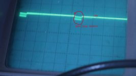
Fig 2 Point 93. Brightnes is at a maximum. Waveform from fig 1 is changed and becomes the new waveform when the voltage at R4109 (midpoint) exceeds 39V.
Your remark that you have a 465B helped me to see better!
I've downloaded from the website service manual for 465B and read the full description for DC restorer, which I have not had in my manual for 465. And more importantly, that there are waveforms 91, 93 and the center tap of T4015 (50kHz), figures 3.10 and 3.11, pages 3.23 and 3.24.
Where I see the problem?
I do not have the appropriate waveform 93 pictures 3.10 and 3.11, diagram B. A diagrams are OK. Please refer to Figure 1 in attachment.
The changes in voltage from 15V to 95V exist like in the diagram 91, and the anode CR4112 (465B), but at the cathode voltage on CR4112 is only part of the T4105, 6Vpp (50kHz). DC level of this voltage varies from 15V to 100 with changes in the brightness, min to max.
When I change the voltage at the trim pot R4109 (CRT Bias), at point 93 of the DC level rises from 0V to 55V when the brightness on the minimum. When the brightness at maximum, Point 93 goes to 100V, and R4198 almost no influence, except very few modulation the voltage (50kHz) with voltage from point 91, see Figure 2.
I checked all the diodes and resistors of about point 93 with DMM. Everything is OK.
I do not know what I did not see
Is this perhaps the other reason why I can not make adjustments to brightness?
l no idea what to do next?
Thanks
Aleksandar
Notes:
Fig.1 Point 93. The brightness is at minimum. Trim pot R4109 is changed from 0 to the maximum. DC level (50kHz) changes from 16.5V to 51,5V.
Fig 2 Point 93. Brightnes is at a maximum. Waveform from fig 1 is changed and becomes the new waveform when the voltage at R4109 (midpoint) exceeds 39V.
Attachments
Hello everyone,
I finally solved the problem of controlling the intensity of brightness. I hope that I can help to everyone with similar problems because I'll explain what happened.
Voltage 300Vpp see XC1420 impedance (47pF) and a resistor R1420 about 800kohm's.
Since the voltage in point: the anode CR1483, CR1482 and cathode resistors R1488, R1420 about 6V, I understand that somewhere in these three branches (left, right and up) small leakage current through the diode, made drop this voltage.
First I removed right side, (easest capacitor C1488), nothing. Then the above, the cathode diode CR1482, nothing. Last is the diode CR1483, where I least suspected. When I separated, the voltage went up to about 170Vpp.
That's it! I did not have at hand the original diode, but I put 3 diodes 1N4148. Now everything is OK!
Now the diagram at this point is absolutely identical as in the service manual for 465B diagram 93.
IMPORTANT NOTE! All diodes (CR1482, 83, 87, 88) I checked them several times with the DMM. All were OK.
At the end, thank you to all who have read this discussion, especially mr. Loudthud who helped me a lot with their advices.
Aleksandar
Serbia
- Status
- Not open for further replies.
- Home
- Design & Build
- Equipment & Tools
- Tektronix 465 Sweep generator