Hello.
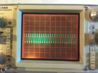
I just got a Tektronix 465 (simple, no B or M) oscilloscope off ebay about 2 weeks ago (~100$) and I was very happy that it worked out of the box with no issue. Very good cosmetic condition, nothing broken even a few extras like original operating manual and service manual (like new condition, from 1978!), an optional blue screen, another wire mesh screen for mechanical protection of the display, frontal case for protection etc. Very very nice.
It was out of calibration so I started looking in the manual. Opened it up and started twisting the pots
I got it right on the 4th attempt when I understood how each adjustment interacts with the other.
Also I've taken my time while constructing a HV divider for the -2450V for CRT 😱
Everything is in spec, some 20 odd mV ripple on the 110V line but nothing else. Power supply right on spot.
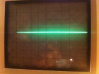
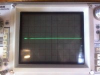
After everything was done I still noticed that I haven't fixed two annoying issues. One is that the horizontal line (while GND coupled) extends to the right outside the area of display and there's nothing that can be done to adjust that (besides messing with X1 gain 😀) That's kind of bad as I like my signal to end at the last vertical line on the display. Anyway, I could live with that but the next problem I faced is even worse:
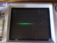
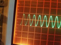
Starting from about 5uS to 0.005uS sweep speeds the horizontal line starts to shrink from both sides, and on the left side I get a kind of faded out signal/line (depending on the coupling state). It doesn't end sharply as it does on slower sweeps. The problem is that I don't know where the trace starts. If I crank the CRT I get more dim signal on the left side but the rest of the signal is so bright that it annoys me.
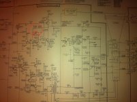
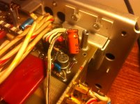
Now I have checked the manual and in the calibration procedure there's this variable capacitor that is meant exactly for this kind of adjustment but the trouble is that the result is minimal, about one microdivision extension. I started checking all of the transistors in the Z-axis amplifier area and they were all good, as in not shorted at least. I replaced Q1466 with a BC549 and Q1472 with a BC556 that I had and that improved the trace by about one division to the left but It's still more bright in the middle and still fades out. Also I cut some resistor's leads so I can test them and most of them do check out. The variable capacitor I could not test as it's 1.5pF but it seems to be doing something in the extremes, and while I touch it with my finger (I guess there's enough capacitance there to make a change).
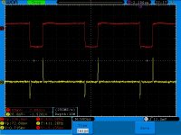
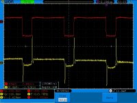
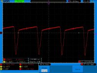
The unblanking signal comes on the emitter of Q1466. That's the red signal in some photos. Refer to the file name for more info on picture.
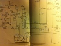
I don't know what else to look for. This is my first oscilloscope (bought it almost the same time with my digital Owon one) so I don't know that much about them but I am capable of basic testing with the other one. If you have some ideas do share them. I added the Z-axis/CRT circuit and some screenshots/pictures from the test oscilloscope and the Tek one.
Where should I look next?
Is there anyone that had this problem before?
P.S.
There are some waveforms present in the manual for troubleshooting, and they all test out perfect in the given test conditions from the manual, the problem is that the manual calls for 1ms sweep speeds for these tests while my problem starts from 5us and get worse to 0.05us.
I just got a Tektronix 465 (simple, no B or M) oscilloscope off ebay about 2 weeks ago (~100$) and I was very happy that it worked out of the box with no issue. Very good cosmetic condition, nothing broken even a few extras like original operating manual and service manual (like new condition, from 1978!), an optional blue screen, another wire mesh screen for mechanical protection of the display, frontal case for protection etc. Very very nice.
It was out of calibration so I started looking in the manual. Opened it up and started twisting the pots
I got it right on the 4th attempt when I understood how each adjustment interacts with the other.
Also I've taken my time while constructing a HV divider for the -2450V for CRT 😱
Everything is in spec, some 20 odd mV ripple on the 110V line but nothing else. Power supply right on spot.
After everything was done I still noticed that I haven't fixed two annoying issues. One is that the horizontal line (while GND coupled) extends to the right outside the area of display and there's nothing that can be done to adjust that (besides messing with X1 gain 😀) That's kind of bad as I like my signal to end at the last vertical line on the display. Anyway, I could live with that but the next problem I faced is even worse:
Starting from about 5uS to 0.005uS sweep speeds the horizontal line starts to shrink from both sides, and on the left side I get a kind of faded out signal/line (depending on the coupling state). It doesn't end sharply as it does on slower sweeps. The problem is that I don't know where the trace starts. If I crank the CRT I get more dim signal on the left side but the rest of the signal is so bright that it annoys me.
Now I have checked the manual and in the calibration procedure there's this variable capacitor that is meant exactly for this kind of adjustment but the trouble is that the result is minimal, about one microdivision extension. I started checking all of the transistors in the Z-axis amplifier area and they were all good, as in not shorted at least. I replaced Q1466 with a BC549 and Q1472 with a BC556 that I had and that improved the trace by about one division to the left but It's still more bright in the middle and still fades out. Also I cut some resistor's leads so I can test them and most of them do check out. The variable capacitor I could not test as it's 1.5pF but it seems to be doing something in the extremes, and while I touch it with my finger (I guess there's enough capacitance there to make a change).
The unblanking signal comes on the emitter of Q1466. That's the red signal in some photos. Refer to the file name for more info on picture.
I don't know what else to look for. This is my first oscilloscope (bought it almost the same time with my digital Owon one) so I don't know that much about them but I am capable of basic testing with the other one. If you have some ideas do share them. I added the Z-axis/CRT circuit and some screenshots/pictures from the test oscilloscope and the Tek one.
Where should I look next?
Is there anyone that had this problem before?
P.S.
There are some waveforms present in the manual for troubleshooting, and they all test out perfect in the given test conditions from the manual, the problem is that the manual calls for 1ms sweep speeds for these tests while my problem starts from 5us and get worse to 0.05us.
Attachments
-
 IMG_0206.JPG608.7 KB · Views: 277
 -
 IMG_0226.JPG208.8 KB · Views: 100
 -
 IMG_0225.JPG104.8 KB · Views: 106
 -
 IMG_0224.JPG317.7 KB · Views: 108
 -
 emitter vs gate Q1466.jpg154.5 KB · Views: 116
 -
 emitter vs collector Q1466.jpg156.3 KB · Views: 117
 -
 0.05us.JPG191.5 KB · Views: 258
 -
 0.1us.jpg73.6 KB · Views: 253
 -
 5us.jpg85.5 KB · Views: 251
 -
 IMG_0210.JPG174 KB · Views: 275
Last edited:
Some of the Tek scopes have a trace width/end control on the front panel.
I'd be wary of caps. I know there are not all that many caps in there, but the most likely thing to change is a cap, OR a carbon comp resistor (also not many of them in there either).
The fact that it gets worse as the sweep gets faster seems to point to a cap or at least a time constant related issue.
That's all I've got.
Likely there are some Tek pros who might chime in.
_-_-
All I have on the front panel are Focus/Astig and Trace Rotation.
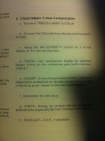
I played around with 3 higher signal sources that I had around and I used for calibration. A tcxo 4mhz square wave, 16mhz sine from Arduino crystal and 24mhz sine from a junk board crystal. The amplitude and frequency are consistent with the digital scope after calibration, so the problem is somewhere in the unblanking circuit I presume. The problem is that mhz signals look bad on display, I can only use the center part from CRT. The freq/amplitude are ok and the trace is sharp and in focus but it's brightness varies across the display and may cause some issues with modulated signals and such.
In the audio range everything seems fine, but still have the extension out on the right side of the display. Maybe I get lucky and both these issues are related somehow.
I used my ESR meter and got good values for the tested capacitors.
I was shooting in the dark for the last two days so I'm hoping someone has seen something like this before.

More progress.
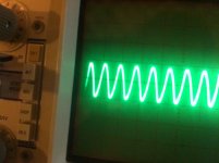
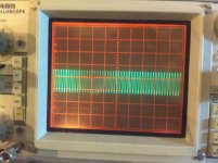
I was looking at signals with digital oscilloscope set on Averaging so I missed the important stuff. On Sample I can see at TP1486 and at Q1466 collector another signal that's piggy-backing on the main unblanking pulse. It's 50khz and it screwing up the signal on faster pulses. Didn't see that on averaging 😱 Live and learn right?
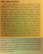
Now I've seen the HV oscillator description and indeed it oscillates at 50khz
Now we're getting somewhere, no more shooting in the dark.
Test point 90 on the schematic shows 316Vpp and I've also measured the + of the C1418/C1419 and it seems that I get about 23V unregulated AND the 50khz signal. On the F1419 fuse I only get the 22V unregulated without the 50khz signal which is kind of ok considering that the schematic shows +15V unregulated.
I also tested C1488 and C1487 and C1420 and they seem ok (tested with LC meter, capacitance in pF range are out of ESR meter possibility and DMM on capacitance can do only out of circuit testing).
Seems like previous owner replaced C1418/C1419 with one 47uF capacitor. I don't know if there were two of them or only a double one or two separate ones.
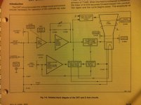
I added oscillator circuit, it's description and some screenshots on the cap's + lead. One with unregulated ripple and another with the 50khz signal.
Now I know what area to scout for the issue. Do share your opinions 😀
I was looking at signals with digital oscilloscope set on Averaging so I missed the important stuff. On Sample I can see at TP1486 and at Q1466 collector another signal that's piggy-backing on the main unblanking pulse. It's 50khz and it screwing up the signal on faster pulses. Didn't see that on averaging 😱 Live and learn right?
Now I've seen the HV oscillator description and indeed it oscillates at 50khz
Now we're getting somewhere, no more shooting in the dark.
Test point 90 on the schematic shows 316Vpp and I've also measured the + of the C1418/C1419 and it seems that I get about 23V unregulated AND the 50khz signal. On the F1419 fuse I only get the 22V unregulated without the 50khz signal which is kind of ok considering that the schematic shows +15V unregulated.
I also tested C1488 and C1487 and C1420 and they seem ok (tested with LC meter, capacitance in pF range are out of ESR meter possibility and DMM on capacitance can do only out of circuit testing).
Seems like previous owner replaced C1418/C1419 with one 47uF capacitor. I don't know if there were two of them or only a double one or two separate ones.
I added oscillator circuit, it's description and some screenshots on the cap's + lead. One with unregulated ripple and another with the 50khz signal.
Now I know what area to scout for the issue. Do share your opinions 😀
Attachments

Reminds me of Z-axis modulation (intensity modulation).... look at waveform fidelity on z-axis path and ripple on cathode.
-RNM
-RNM
Hello.
I just got a Tektronix 465 (simple, no B or M) oscilloscope off ebay about 2 weeks ago (~100$) and I was very happy that it worked out of the box with no issue. Very good cosmetic condition, nothing broken even a few extras like original operating manual and service manual (like new condition, from 1978!), an optional blue screen, another wire mesh screen for mechanical protection of the display, frontal case for protection etc. Very very nice.
It was out of calibration so I started looking in the manual. Opened it up and started twisting the pots
I got it right on the 4th attempt when I understood how each adjustment interacts with the other.
Also I've taken my time while constructing a HV divider for the -2450V for CRT 😱
Everything is in spec, some 20 odd mV ripple on the 110V line but nothing else. Power supply right on spot.
After everything was done I still noticed that I haven't fixed two annoying issues. One is that the horizontal line (while GND coupled) extends to the right outside the area of display and there's nothing that can be done to adjust that (besides messing with X1 gain 😀) That's kind of bad as I like my signal to end at the last vertical line on the display. Anyway, I could live with that but the next problem I faced is even worse:
Starting from about 5uS to 0.005uS sweep speeds the horizontal line starts to shrink from both sides, and on the left side I get a kind of faded out signal/line (depending on the coupling state). It doesn't end sharply as it does on slower sweeps. The problem is that I don't know where the trace starts. If I crank the CRT I get more dim signal on the left side but the rest of the signal is so bright that it annoys me.
Now I have checked the manual and in the calibration procedure there's this variable capacitor that is meant exactly for this kind of adjustment but the trouble is that the result is minimal, about one microdivision extension. I started checking all of the transistors in the Z-axis amplifier area and they were all good, as in not shorted at least. I replaced Q1466 with a BC549 and Q1472 with a BC556 that I had and that improved the trace by about one division to the left but It's still more bright in the middle and still fades out. Also I cut some resistor's leads so I can test them and most of them do check out. The variable capacitor I could not test as it's 1.5pF but it seems to be doing something in the extremes, and while I touch it with my finger (I guess there's enough capacitance there to make a change).
The unblanking signal comes on the emitter of Q1466. That's the red signal in some photos. Refer to the file name for more info on picture.
I don't know what else to look for. This is my first oscilloscope (bought it almost the same time with my digital Owon one) so I don't know that much about them but I am capable of basic testing with the other one. If you have some ideas do share them. I added the Z-axis/CRT circuit and some screenshots/pictures from the test oscilloscope and the Tek one.
Where should I look next?
Is there anyone that had this problem before?
P.S.
There are some waveforms present in the manual for troubleshooting, and they all test out perfect in the given test conditions from the manual, the problem is that the manual calls for 1ms sweep speeds for these tests while my problem starts from 5us and get worse to 0.05us.
Last edited:
Reminds me of Z-axis modulation (intensity modulation).... look at waveform fidelity on z-axis path and ripple on cathode.
-RNM
Are you referring to this picture? The unblanking pulse comes in Z amplifier area first in Q1466 on it's emitter then on the collector I get the same distorted waveform. And that's because on that side I have the 50khz signal that's leaking from the HV oscillator. The problem is I don't know where exactly is leaking. HV oscillator is at 50khz exactly like the small signal contaminating the unblanking pulse on the collector side of Q1466.
Are you referring to this picture? The unblanking pulse comes in Z amplifier area first in Q1466 on it's emitter then on the collector I get the same distorted waveform. And that's because on that side I have the 50khz signal that's leaking from the HV oscillator. The problem is I don't know where exactly is leaking. HV oscillator is at 50khz exactly like the small signal contaminating the unblanking pulse on the collector side of Q1466.
Attachments

We still have some older Tek scopes at work. But better than that, we have some original parts and one of my 'older' coworkers is pretty good with their repair. He is on vacation Friday, but I can ask him on Monday if he has seen this before.
Dave
Dave
Thanks Dave, I'd appreciate that. I'll let you know if I figure it out until Monday.
I like this as it's interesting. I get to go through all the circuit especially in the Z-axis/HV area 🙂
I like this as it's interesting. I get to go through all the circuit especially in the Z-axis/HV area 🙂
No problem. I used to have a 468, but it had a major time base issue. I think a previous owner tried a repair and caused some major issues. I lived with the issue for a long time. I bought a digital scope and it's ok, but I have a Tek 2230 to use now as well. I still like analog scopes for audio.
Dave
Dave
Thanks Dave, I'd appreciate that. I'll let you know if I figure it out until Monday.
I like this as it's interesting. I get to go through all the circuit especially in the Z-axis/HV area 🙂
I suggest you join the Tekscopes Yahoo group Yahoo Groups and ask your question there. Some Tek experts frequent that group and are very good about helping out.
join the tek group on yahoo groups. Lots of experts including many ex-tek engineers.
TekScopes@yahoogroups.com
TekScopes@yahoogroups.com
Yes, it's done!
It was Q358 transistor on the vertical preamp board.
The voltage on it's base was about +1.31V instead of +0.8V.
I have replaced that and now everything is fine. I'm still missing about a division at 0.05us sweep speed but I can live with that. Down at 0.5us I have the full trace. And the trace is evenly illuminated at all sweep speeds.
I couldn't have pulled this off without the help of the super great guys over at TekScopes yahoo group. Those guys are pros at this kind of stuff Also they have given me a lot of info that I still need to sort out. It's been a great experience
It was Q358 transistor on the vertical preamp board.
The voltage on it's base was about +1.31V instead of +0.8V.
I have replaced that and now everything is fine. I'm still missing about a division at 0.05us sweep speed but I can live with that. Down at 0.5us I have the full trace. And the trace is evenly illuminated at all sweep speeds.
I couldn't have pulled this off without the help of the super great guys over at TekScopes yahoo group. Those guys are pros at this kind of stuff
Also they have given me a lot of info that I still need to sort out. It's been a great experience An externally hosted image should be here but it was not working when we last tested it.
An externally hosted image should be here but it was not working when we last tested it.
An externally hosted image should be here but it was not working when we last tested it.
Guessing the rise time on that transistor is still a bit slow... maybe the ft of the actual transistor or still there is something slightly off in that area?
I was looking at the rise time as well. I also added a clamping diode but no improvement. I still don't know if the issue is from the z-axis amp or before it. I will do some more tests comparing the rise times of both pulses at various speeds.
- Status
- Not open for further replies.
- Home
- Design & Build
- Equipment & Tools
- Tektronix 465 horizontal issue