Part 1
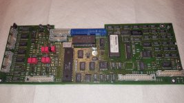
I am having a nice Tek 2465BCT on my plate with an issue I am stuck with. I am hoping someone has tripped over that problem before. The scope came with a GPIB option, for troubleshooting, I have this option board removed.
Here is a description of what symptoms I see.:
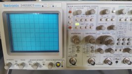
On power up the scope seem to get stuck with ADD Led on, blank CRT - no display. However, if the scope is left on for a while there is a very dim and faint display readable.
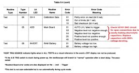
TEST 05 FAIL 40
Acknowledging this error makes it seem to complete boot process. However trace position knobs do not seem to work properly and CRT display still extremely dim.
Entering Test Mode manually and rerunning TEST 05 now fails with 44.
Additional Tests CT TEST 86 FAIL 02 and CT TEST 87 FAIL 18 as well.
For now I am focusing on TEST 05 Failure.
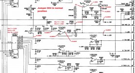
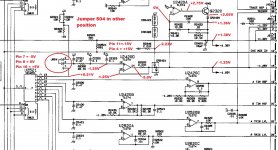
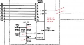
Eventually I traced this issue to the A5 Controller board, Voltages for the +1.36V and -1.25V rails seems bad. Please see my measurements with Jumper 504 in normal position vs. Jumper 504 in other position. At this point I am not understanding why it seem necessary to create these voltages dynamically with the DAC U2101 and MUX U2521. What is the purpose of Jumper 504 ?
I have yet not found anything on this jumper in the service manual.
With Jumper 504 in other position I do get the proper rail voltages as expected, CRT brightness is very bright, but readout brightness and trace brightness are not controllable with the knobs anymore. Also trace position and cursor position does not work properly.
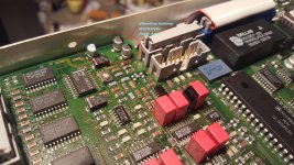
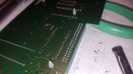
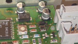
On visual inspection there is one X7R decoupling capacitor which has some black grime around it but I do not suspect this to be the problem. I tried to clean this off with Isopropyl and a Q-Tip. What ever it is, its not coming off easy. I will try with a tooth brush again. Also on resistor R2014 there was a slight green discoloration on one solder joint, not sure what that could be. I tried to clean this off as well. I did notice the solder joints in this DAC area look not really appealing to me, they look dull as if they were cold joints. I am not sure if back than Tektronix used lead-free solder. The joints look actually really crappy to me. I tried to re-solder the worst joints using tin-lead solder and rosin flux but for some reason the solder joints still look not great. I am not sure if there is some contamination preventing a decent solder flow. (turned out electrolyte of nearby capacitors escaped and contaminated the area)
When I poke around this DAC circuit and aggravating using cold spray, I can sort of provoke the problem to come and go intermittently. At this point I can not put my finger on it what exactly is causing this as this is getting a little weird.
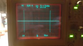
I checked the DAC signals B1 to B12, they look good to me altho I can not verify the streaming logic values. But for the moment I think they are just fine. I looked the the DAC output Pin 18 and Pin 19 (D, E), I see various analog levels as I would expect, however the overall amplitude seems unstable. I am not sure what the peak to peak amplitude should be, maybe someone knows. Sometimes I see about 1.4Vpp sometimes a lot less about 0.6Vpp or even less than that. I can observe the trace brightness, readout brightness and trace position so as delta time cursors going crazy on the CRT. This is consistent with my understanding how the 1.36V and -1.25V rail is used in this scope. If this is unstable so is everything else.
If I manage to get it stable for the moment, I get the scope to pass all self tests. Good news.")
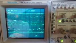
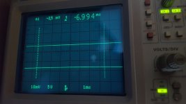
Poking around scoping points A, B and C, I see bad flicker noise of several milli volts.
So I
Re-soldered R2016, did not impact the problem
Replaced C2010 with an electrolytic cap, did not impact the problem
Replaced R2016, did not impact the problem
Re-soldered R2012, did not impact the problem
Double checked the 10V Reference voltage at R2016, looks good.
DAC Pin 20, +5V looks good,
DAC Pin 17, -15V looks good,
DAC Pin 13, 0V looks good.
So at this point I am convinced the DAC circuit is the offender. I am leaning to replace all the passive components around the DAC chip including the pot R2010, but then I will have to recal this DAC circuit which I would like to avoid having to do.
What are the odds that the 20k Pot R2010 went bad ?
What are the odds the DAC chip U2101 is flaky ?
As I noticed that the DAC signal amplitude (D, E) seems to increase if I put my finger on the DAC chip for a while.
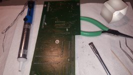
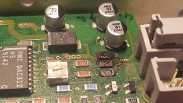
I think I found the issue. As per schematic R2012 is connected to GND and to the 20K Pot R2010. Eventually I took the 10K Resistor R2012 (the one with possibly bad solder joint) off the board and I did some ringing with my meter.
Turns out the connection from R2012 to Pot R2010 did not exist (anymore).
I reinstalled R2012 and put a small wire from R2012 to Pot R2010. Powered up the scope and .... Problem gone.
Scope passes all self tests. The CRT is as crisp as as ever.
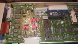
So far I have rarely seen board failures, this is a classic one. Signal traces are for my taste too thin in this area and perhaps, my guess there could have been an acid trap lingering eating the trace away over time.
So I did some measurements and documented the measured correct voltages, this might help someone else troubleshoot this problem since this DAC problem is not covered in the Tektronix troubleshooting guide.
I believe TEST 05 failures may very well all originate in the DAC circuit with this board failure due to leaking capacitors. Turns out this is a very common problem with the 2465 series scopes.
The electrolytic capacitors on A5 board should be replaced with higher voltage rated, low ESR capacitors of the same or higher capacitance that fit the available board space / footprint.
C2011 suggested 33uF/35V
C2331 suggested 22uF/50V
C2113 suggested 22uF/50V
C2965 suggested 22uF/50V
Not necessary but optional replace tantalum capacitors (15uF/25V)
C2010 suggested 33uF/35V
C2420 suggested 33uF/35V
C2350 suggested 33uF/35V
Soja, I failed to ask
what are the odds of a board failure ?
Part 2 --> NVRAM Cal Data rescue.

I am having a nice Tek 2465BCT on my plate with an issue I am stuck with. I am hoping someone has tripped over that problem before. The scope came with a GPIB option, for troubleshooting, I have this option board removed.
Here is a description of what symptoms I see.:
On power up the scope seem to get stuck with ADD Led on, blank CRT - no display. However, if the scope is left on for a while there is a very dim and faint display readable.
TEST 05 FAIL 40
Acknowledging this error makes it seem to complete boot process. However trace position knobs do not seem to work properly and CRT display still extremely dim.
Entering Test Mode manually and rerunning TEST 05 now fails with 44.
Additional Tests CT TEST 86 FAIL 02 and CT TEST 87 FAIL 18 as well.
For now I am focusing on TEST 05 Failure.
Eventually I traced this issue to the A5 Controller board, Voltages for the +1.36V and -1.25V rails seems bad. Please see my measurements with Jumper 504 in normal position vs. Jumper 504 in other position. At this point I am not understanding why it seem necessary to create these voltages dynamically with the DAC U2101 and MUX U2521. What is the purpose of Jumper 504 ?
I have yet not found anything on this jumper in the service manual.
With Jumper 504 in other position I do get the proper rail voltages as expected, CRT brightness is very bright, but readout brightness and trace brightness are not controllable with the knobs anymore. Also trace position and cursor position does not work properly.
On visual inspection there is one X7R decoupling capacitor which has some black grime around it but I do not suspect this to be the problem. I tried to clean this off with Isopropyl and a Q-Tip. What ever it is, its not coming off easy. I will try with a tooth brush again. Also on resistor R2014 there was a slight green discoloration on one solder joint, not sure what that could be. I tried to clean this off as well. I did notice the solder joints in this DAC area look not really appealing to me, they look dull as if they were cold joints. I am not sure if back than Tektronix used lead-free solder. The joints look actually really crappy to me. I tried to re-solder the worst joints using tin-lead solder and rosin flux but for some reason the solder joints still look not great. I am not sure if there is some contamination preventing a decent solder flow. (turned out electrolyte of nearby capacitors escaped and contaminated the area)
When I poke around this DAC circuit and aggravating using cold spray, I can sort of provoke the problem to come and go intermittently. At this point I can not put my finger on it what exactly is causing this as this is getting a little weird.
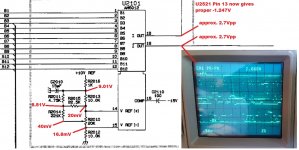
I checked the DAC signals B1 to B12, they look good to me altho I can not verify the streaming logic values. But for the moment I think they are just fine. I looked the the DAC output Pin 18 and Pin 19 (D, E), I see various analog levels as I would expect, however the overall amplitude seems unstable. I am not sure what the peak to peak amplitude should be, maybe someone knows. Sometimes I see about 1.4Vpp sometimes a lot less about 0.6Vpp or even less than that. I can observe the trace brightness, readout brightness and trace position so as delta time cursors going crazy on the CRT. This is consistent with my understanding how the 1.36V and -1.25V rail is used in this scope. If this is unstable so is everything else.
If I manage to get it stable for the moment, I get the scope to pass all self tests. Good news.
Poking around scoping points A, B and C, I see bad flicker noise of several milli volts.
So I
Re-soldered R2016, did not impact the problem
Replaced C2010 with an electrolytic cap, did not impact the problem
Replaced R2016, did not impact the problem
Re-soldered R2012, did not impact the problem
Double checked the 10V Reference voltage at R2016, looks good.
DAC Pin 20, +5V looks good,
DAC Pin 17, -15V looks good,
DAC Pin 13, 0V looks good.
So at this point I am convinced the DAC circuit is the offender. I am leaning to replace all the passive components around the DAC chip including the pot R2010, but then I will have to recal this DAC circuit which I would like to avoid having to do.
What are the odds that the 20k Pot R2010 went bad ?
What are the odds the DAC chip U2101 is flaky ?
As I noticed that the DAC signal amplitude (D, E) seems to increase if I put my finger on the DAC chip for a while.
I think I found the issue. As per schematic R2012 is connected to GND and to the 20K Pot R2010. Eventually I took the 10K Resistor R2012 (the one with possibly bad solder joint) off the board and I did some ringing with my meter.
Turns out the connection from R2012 to Pot R2010 did not exist (anymore).
I reinstalled R2012 and put a small wire from R2012 to Pot R2010. Powered up the scope and .... Problem gone.
Scope passes all self tests. The CRT is as crisp as as ever.
So far I have rarely seen board failures, this is a classic one. Signal traces are for my taste too thin in this area and perhaps, my guess there could have been an acid trap lingering eating the trace away over time.
So I did some measurements and documented the measured correct voltages, this might help someone else troubleshoot this problem since this DAC problem is not covered in the Tektronix troubleshooting guide.
I believe TEST 05 failures may very well all originate in the DAC circuit with this board failure due to leaking capacitors. Turns out this is a very common problem with the 2465 series scopes.
The electrolytic capacitors on A5 board should be replaced with higher voltage rated, low ESR capacitors of the same or higher capacitance that fit the available board space / footprint.
C2011 suggested 33uF/35V
C2331 suggested 22uF/50V
C2113 suggested 22uF/50V
C2965 suggested 22uF/50V
Not necessary but optional replace tantalum capacitors (15uF/25V)
C2010 suggested 33uF/35V
C2420 suggested 33uF/35V
C2350 suggested 33uF/35V
Soja, I failed to ask
what are the odds of a board failure ?
Part 2 --> NVRAM Cal Data rescue.
Attachments
-
 _20190624_123526.jpg701.1 KB · Views: 388
 -
 _20190625_110724.jpg616.9 KB · Views: 434
 -
 Issue_1_J504_normal_12.jpg291.3 KB · Views: 388
 -
 Issue_1_J504_other_23.jpg305.4 KB · Views: 383
 -
 DAC_2.jpg132.1 KB · Views: 411
 -
 DAC_3_issue_fixed.jpg231.8 KB · Views: 229
 -
 _20190626_122030.jpg945.6 KB · Views: 230
 -
 _20190626_132507.jpg394.2 KB · Views: 216
 -
 Error Table_1.jpg164.9 KB · Views: 238
Part 2:
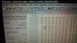
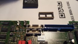
Well, Part 2 is just routine NVRAM service. I removed the Dallas 1225 NVRAM chip and programmed a new replacement chip, easy. Of course this is a little too boring so I poked around the data to see where the hour counter and power cycle values are held. The bits stood out like a sore thumb.
Well, Part 2 is just routine NVRAM service. I removed the Dallas 1225 NVRAM chip and programmed a new replacement chip, easy. Of course this is a little too boring so I poked around the data to see where the hour counter and power cycle values are held. The bits stood out like a sore thumb.
Attachments
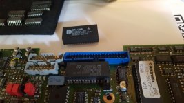
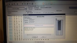
Well, after having Chris's 2465BCT repaired and an opportunity to play with it, I was bitten by the bug and managed to snipe one for myself on ebay in mint condition. When I got my very own 2465BCT I tested it right away for this nagging fault. Turns out it works just fine and it has recent cal stickers on it. Anyhow, I decided to open it up and have a peek at the A5 board that gave the trouble with anatech's. Sure enough mine looks to have the exact same problem but no traces have rotten away, yet. So I gave it the same treatment, removed the electrolytics and replaced them with higher voltage derated once. Also, since having the board removed, I replaced the Dallas NVRAM chip as well. Mine was vintage 1992 and still kept the data but it is time to save the cal data. Now, this scope is all done and hopefully it remains in service for another 25 years.
Attachments
-
 _20200112_181314.jpg392.1 KB · Views: 106
 -
 _20200112_173407.jpg606.5 KB · Views: 89
 -
 _20200112_165811.jpg545.8 KB · Views: 88
 -
 _20200112_165805.jpg582.1 KB · Views: 109
 -
 _20200112_143410.jpg612.3 KB · Views: 109
 -
 _20200112_143348.jpg560.5 KB · Views: 153
 -
 _20200112_143339.jpg586.2 KB · Views: 119
 -
My_A5U2460_Dallas_NVRAM_DS1225Y-200_Checksum_0014D493.zip2.1 KB · Views: 38
The replacement ST RAM chips you used seem to have a 1993 date code.
The battery life would be suspect, nyet?
Here is a nice compendium of info on the topic -
http://worldphaco.com/uploads/TEKTRONIX_2465b_OSCILLOSCOPE_CALIBRATION___REPOWERING_THE_DS1225.pdf
The battery life would be suspect, nyet?
Here is a nice compendium of info on the topic -
http://worldphaco.com/uploads/TEKTRONIX_2465b_OSCILLOSCOPE_CALIBRATION___REPOWERING_THE_DS1225.pdf
Hi quadtech,
Could be perhaps date code 1999, I am not sure. These chips I had were new old stock, it be interesting to see if it last any longer. Goal of this exercise was to get the data read out before the chip looses it and put a socket on the board.
Thanks for sharing the document. It is quite in depth, now that I have the data and a socket I could explore some of the options suggested in the document you had posted.
Good stuff !
Attachments
Last edited:
KCT, yes now that you have a copy of the data, you can play with it.
The FRAM could be worth a try. I am sure you have gone over the huge 2465
thread over on eevblog. I am linking it here as a convenient reference -
Tektronix 2465B oscilloscope teardown - Page 1
The FRAM could be worth a try. I am sure you have gone over the huge 2465
thread over on eevblog. I am linking it here as a convenient reference -
Tektronix 2465B oscilloscope teardown - Page 1
- Status
- This old topic is closed. If you want to reopen this topic, contact a moderator using the "Report Post" button.
- Home
- Design & Build
- Equipment & Tools
- Tektronix 2465BCT Test 05 Fail xx (issue solved)