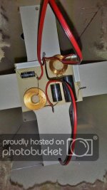
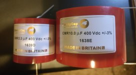
You can design the crossover yourself. The original XO looks to be a simple 2nd order with a Zobel network on the woofer (that would be the electrolytic cap and resistor seen since its in parallel).
The Audax Gold dome tweeter can be crossed at 2kHz with a resistor L-pad - the resistor seen probably mitigate the energy or SPL output since the Tekton driver is more than likely at least 3dB lower in sensitivity.
If you have the Tekton driver but don't have the data sheet, measure its T/S parameters which will help you design its filter.
Hope that helps
Last edited:

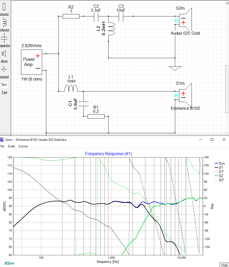
Using the Eminence B102 woofer and the Audax 025Gold tweeter ( along with the previously posted cap values ) one can ascribe these values to a network;
🙂
🙂
Attachments
Last edited:
I would also like to try a two way with a 10” driver, is that b102 driver better soundwise then seas a26.
I think R2 goes after C3.
I agree. 😀
Relocate R2 so that it's after C3 , then increase is value to 2 ohms, results in a slightly smoother response in the crossover area .
🙂
Last edited:
Looking for help Tekton Enzo Xover
Hello Everyone, this is the closest thread i have found to the issue I'm dealing with. Perhaps someone can lend me a hand.
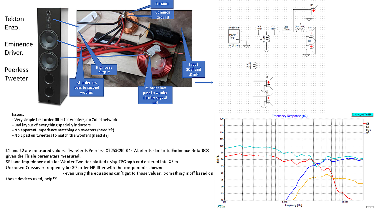
I have a tekton Enzo original (see attached info) with crossover values that I'm having trouble making sense of. I have tried to use the Xover equations to reverse engineer the Xover points of the HP section; I have used XSim to similate the network (attached). Either way I'm not sure what this point is. The first order LP for the woofers is pretty clear but even there the Sim does not look right. On top of this, the Xover seems to have a pretty poor layout for the inductors.
I was hoping to upgrade parts and improve layout but first need to understand this design better. I have measured the inductors with a LCR meter and using an oscilloscope method, values match. I used the manufacturers data to create SPL and Impedance files for Xsim and I even measured the Thiele parameters for the Woofer which seems to match the Eminence 8-BetaCX unit.
If I run a 3rd order filter program the values are all way off, even if I assume a second order followed by a first order I still cannot get this combination of Capacitors and Inductor values. thank you in advance.
Hello Everyone, this is the closest thread i have found to the issue I'm dealing with. Perhaps someone can lend me a hand.
I have a tekton Enzo original (see attached info) with crossover values that I'm having trouble making sense of. I have tried to use the Xover equations to reverse engineer the Xover points of the HP section; I have used XSim to similate the network (attached). Either way I'm not sure what this point is. The first order LP for the woofers is pretty clear but even there the Sim does not look right. On top of this, the Xover seems to have a pretty poor layout for the inductors.
I was hoping to upgrade parts and improve layout but first need to understand this design better. I have measured the inductors with a LCR meter and using an oscilloscope method, values match. I used the manufacturers data to create SPL and Impedance files for Xsim and I even measured the Thiele parameters for the Woofer which seems to match the Eminence 8-BetaCX unit.
If I run a 3rd order filter program the values are all way off, even if I assume a second order followed by a first order I still cannot get this combination of Capacitors and Inductor values. thank you in advance.
Attachments
Hi,
Here's your pdf ( 1st page ) turned into a pic.
You might also want to post your XSim file ( either zipped or as a straight .dxo ) .
The electrical and acoustical slopes of the woofer circuit combine to approximate that of the Tweeters circuit ( after mentally removing that "horn" seen at around 5K ).
The displayed "hole" at crossover is most likely not that bad ( once you enter in a reasonable "Z offset" for those woofers ( try 3" ).
I see no reason for more padding in the tweeter circuit ( from the simulation ).
- Do you find the tweeters too loud ?
🙂
Attachments
Last edited:
Thank you for the feedback, attached is the DXO file. I will try your suggestion at the same time I really wish to understand the design that Tekton did here, at this point all I can do is simulate the response but cannot figure out the engineering logic being the values selected on the HP section.
Tweeter or better said, the system, seem brighter that I feel it should be, it is also a bit muddle, this might be due to perhaps the driver quality.
Also, the tweeter arrangement is such that the top and bottom tweeters are low passed, seems to be something Teckton uses regularly on their tweeter arrays perhaps to similate some sort of mid-range response?
Once again appreciate your quick response. Thank you.
Attachments
Thanks,
There are problems with 2 of your impedance files.
The Eminence woofer zma file is full of zeros ( in the second and third columns ).
- The second column sets the impedance value per frequency of the first column.
The Peerless tweeter found in S3 has a nominal impedance of 53 ohms ( quite unlikely!! ).
🙂
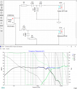
Thanks again EAarlK, not sure what happened when I did the trace; retraced the plots and now the impedance curves match the datasheets. I also see that the Xover plots look more "reasonable". I attached a pic and DXO of this run with the new retraced ZMA and FRD files.
Now the question is about the cross over point, perhaps it needs some adjustment to a lower point. Anyways, appreciate your recommendations and thank you for helping me with this homework.
Miguel
Now the question is about the cross over point, perhaps it needs some adjustment to a lower point. Anyways, appreciate your recommendations and thank you for helping me with this homework.
Miguel
Attachments
@Migueldayer
Do you have a test mic?
You're going to need a mic ( as well as software such as REW ) so that you can make ( & monitor ) meaningful changes.
It would be simpler for you to sell these speakers ( since they obviously disappoint you ) and buy something that you like.
🙂
Do you have a test mic?
You're going to need a mic ( as well as software such as REW ) so that you can make ( & monitor ) meaningful changes.
It would be simpler for you to sell these speakers ( since they obviously disappoint you ) and buy something that you like.
🙂
Thanks EarlK, I have measured the speakers with REW and miniDSP UMIK-1 mic, I will play around with the crossover characteristics until I get it right (actual Vs sim) then will see where it takes me. I agree, perhaps I need to move into something else but I like to tinker so will tinker a bit 🙂.
BR, Miguel
BR, Miguel
Hi Miguel,
Since you can measure drivers you should be using some real measurements ( taken with drivers in place, in cabinent ).
Anyways, here are ( a couple pieces of real science fiction ) for you to peruse.
- They are just guesses since they don't use real measurements of your drivers as implemented.
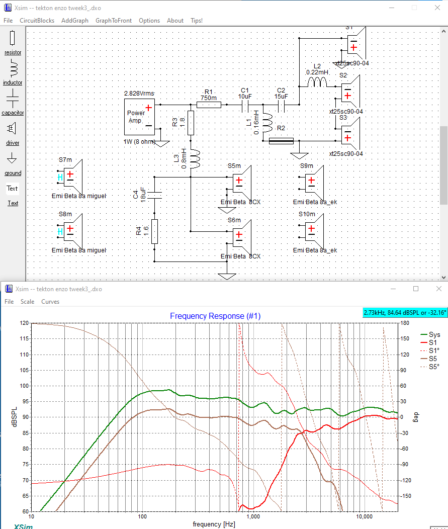
"tweek3" uses the Beta8 CX while variant "tweek4" uses the Beta8 8a freq. responses ( as published by Eminence ) .
I created my own traces since yours lack the necessary phase information.
- You should start using the trace tool found in VituixCAD2 ( it's superior to all others IME ).
Arbitrarily ( based on a visual ), I reduced the output of the 8" woofers by putting some inline resistance.
- The resistor ( R3 ) and DCR of the coil add up to be 2 ohms.
- Any resistor in this position ( + that caution includes R1 ) needs to be beefy ( iow; 20-40 watts > dependent on ones playback level ).
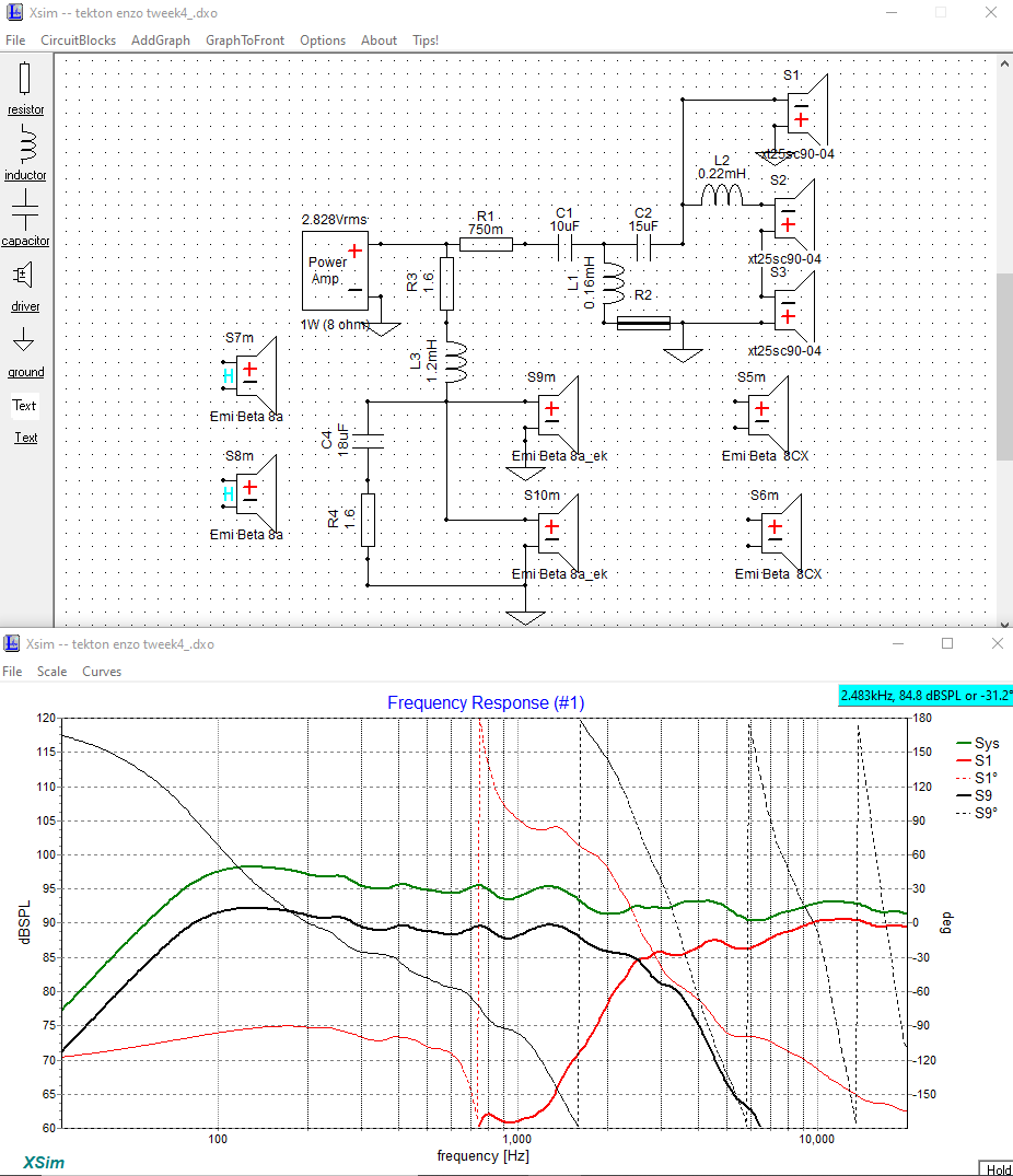
Both of these versions have pretty mediocre phase tracking between components ( @ 90deg ).
- This is also based on the woofer's acoustic centre being about 1.75" behind the tweeters ( I made a mechanical measurement, iow; an educated guess timate ).
- You should put some effort into acquiring ( measuring ) the Z Offset for your drivers .
- You'll need to study the works of Jeff Bagby and other/or others who use WinPCN or PCN7 .
🙂
Since you can measure drivers you should be using some real measurements ( taken with drivers in place, in cabinent ).
Anyways, here are ( a couple pieces of real science fiction ) for you to peruse.
- They are just guesses since they don't use real measurements of your drivers as implemented.
"tweek3" uses the Beta8 CX while variant "tweek4" uses the Beta8 8a freq. responses ( as published by Eminence ) .
I created my own traces since yours lack the necessary phase information.
- You should start using the trace tool found in VituixCAD2 ( it's superior to all others IME ).
Arbitrarily ( based on a visual ), I reduced the output of the 8" woofers by putting some inline resistance.
- The resistor ( R3 ) and DCR of the coil add up to be 2 ohms.
- Any resistor in this position ( + that caution includes R1 ) needs to be beefy ( iow; 20-40 watts > dependent on ones playback level ).
Both of these versions have pretty mediocre phase tracking between components ( @ 90deg ).
- This is also based on the woofer's acoustic centre being about 1.75" behind the tweeters ( I made a mechanical measurement, iow; an educated guess timate ).
- You should put some effort into acquiring ( measuring ) the Z Offset for your drivers .
- You'll need to study the works of Jeff Bagby and other/or others who use WinPCN or PCN7 .
🙂
Attachments

Last edited:
Wow! Much appreciated EarlK, at this point I have plenty to digest and work with. I'll post something down the road as I slowly work around all the options. will also look at the VituixCAD2 tool. Thank you.
Anyone have a xo design for the Tekton Lore Reference please? It's a smaller version, between the Lore and the Mini.
Hi all! would someone know the steps to remove the lore crossover from the enclosure to tweak it and put it back in? I don't wan't to damage anything. Tx
- Home
- Loudspeakers
- Multi-Way
- Tekton Lore Crossover